Light enhanced tray type bridge stand

An enhanced, tray-type technology, applied in electrical components and other directions, can solve problems such as affecting the anti-corrosion performance and service life of the bridge, prone to gaps in the connection parts, and many processing procedures, so as to achieve firm and reliable welding parts, increase heat dissipation, and ensure The effect of assembly precision

Inactive Publication Date: 2017-07-21
JIANGSU ONEQ ELECTRICAL APPLIANCE GRP
View PDF4 Cites 4 Cited by
  • Summary
  • Abstract
  • Description
  • Claims
  • Application Information

AI Technical Summary

Problems solved by technology

[0002] Cable trays are widely used in engineering construction. After 30 years of development, the products have been continuously updated, from general processing of shearing, folding and punching to cold bending forming and molding process changes. The product structure has changed from flat plate structure to corrugated structure, molded reinforced riveting structure and high strength corrugated. structure, etc., so that the product has been well improved in terms of performance and effective use of resources, but these technologies still have deficiencies, such as corrugated structure and molded reinforced riveted structure, which cannot be effectively used according to the different load distribution of side plates and bottom plates. Resources: Although the high-strength corrugated structure has high utilization efficiency of the board, there is still a lot of room for improvement in the process and structure. For example, the length of the bottom plate is 250mm, the splicing is short, there are many processing procedures and the cumulative error is large, and the accuracy is not high. , the connection part is prone to gaps, and the splicing part is thin and easy to deform, which affects the appearance. In addition, the groove part is integrated with the side plate, and it is not easy to discharge after water accumulation, which affects the anti-corrosion performance and service life of the bridge.

Method used


Image

  • Light enhanced tray type bridge stand
  • Light enhanced tray type bridge stand
  • Light enhanced tray type bridge stand

Examples


Embodiment Construction

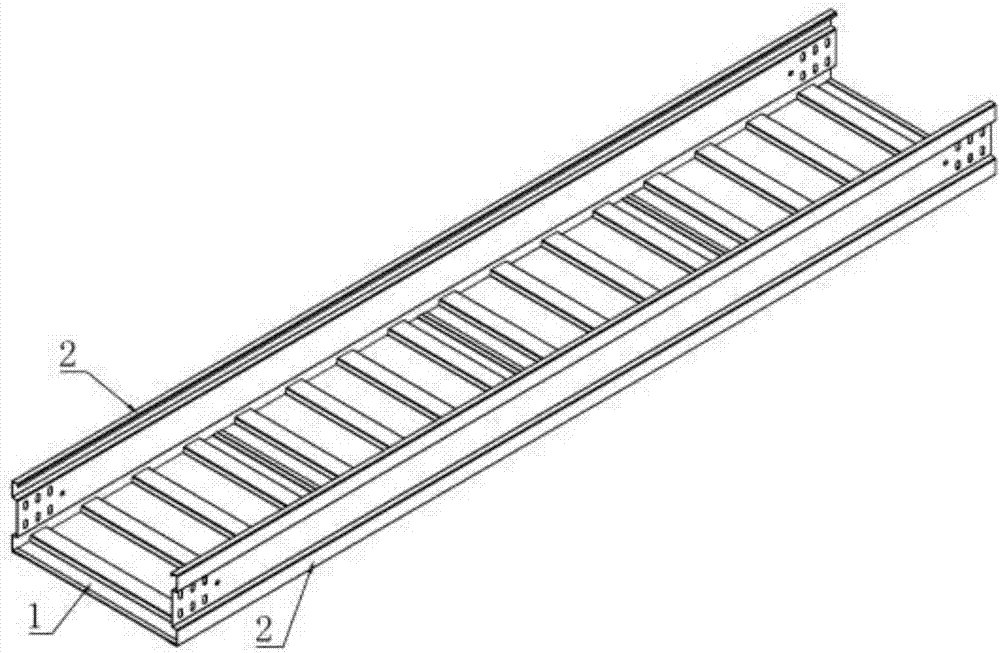
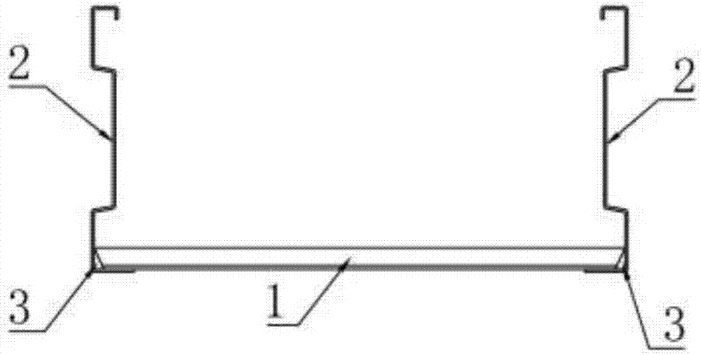
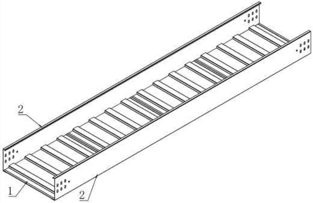
[0022] A light-duty reinforced pallet-type bridge frame of the present invention is composed of two side plates 2 and multiple bottom plates 1. The side plates 2 and bottom plates 1 are formed by cold bending. figure 2 , 4 , 6, 8 and other structures, the bottom plate 1 is spliced ​​continuously along the length direction of the side plate 2 to form a bridge frame, the length of each bottom plate is 500mm, and there are four protrusions 11, and the two ends of the bottom plate are folded out 3 ~ 20mm The width of the bottom plate 1 is cut according to the specifications of the bridge, and the cutting angle is obliquely cut, that is, the width of the upper plane in the transverse direction of the base plate 1 is greater than the width of the lower plane, so that the transverse width of the bottom groove 12 is smaller than the transverse width of the protrusion 11. 15mm, so that there is a certain gap 3 at the bottom when the bottom plate 1 and the side plate 2 are connected, a...


PUM


Abstract

The present invention is a light-duty enhanced tray-type bridge frame, which consists of two side plates (2) and a plurality of bottom plates (1). The bottom plate (1) is located between the two side plates (2), and along the side plates (2) A plurality of pieces are spliced ​​continuously in the inner length direction to form a bridge frame. The width of the bottom plate (1) is cut according to the specifications of the bridge frame. The cutting angle of the bottom plate (1) is obliquely cut, that is, the width of the upper plane in the transverse direction of the bottom plate (1) is greater than the width of the lower plane , so that the transverse width of the bottom groove (12) is smaller than the width of the protrusion (11), so that there is a certain gap (3) at the bottom connection between the bottom plate (1) and the side plate (2), and finally the bottom plate (1) and the side plate Plate (2) is assembled and welded into a whole. Compared with existing products, it is light in weight, high in strength, easy to process, eliminates cumulative errors, and the splicing parts are not easily deformed. It solves the problem of zinc liquid deposits in the groove of the bottom plate during hot-dip galvanizing, is not easy to accumulate water at the bottom, and has high resource utilization. .

Description

technical field [0001] The invention relates to a tray-type cable bridge used for engineering such as electric power or communication cables, and belongs to the technical field of electrical accessories. Background technique [0002] Cable trays are widely used in engineering construction. After 30 years of development, the products have been continuously updated, from general processing of shearing, folding and punching to cold bending forming and molding process changes. The product structure has changed from flat plate structure to corrugated structure, molded reinforced riveting structure and high strength corrugated. structure, etc., so that the product has been well improved in terms of performance and effective use of resources, but these technologies still have deficiencies, such as corrugated structure and molded reinforced riveted structure, which cannot be effectively used according to the different load distribution of side plates and bottom plates. Resources: Al...

Claims


Application Information

Patent Timeline
Patent Type & Authority Applications(China)
IPC IPC(8): H02G3/04
CPCH02G3/0406
Inventor 马纪财马松涛
Owner JIANGSU ONEQ ELECTRICAL APPLIANCE GRP
Why Eureka
Try Eureka