
Fixing and bonding device for swing plate belt of commercial rotary form printing machine

A technology for printing machines and forms, applied in applications, belts, household appliances, etc., can solve the problems of time-consuming, difficult to control the bonding strength, and bump bonding at the bonding points

Inactive Publication Date: 2017-07-25
黑龙江省国家税务局票证站
View PDF3 Cites 0 Cited by
  • Summary
  • Abstract
  • Description
  • Claims
  • Application Information

AI Technical Summary

Problems solved by technology

[0002] Gongyao Commercial Rotary Form Printing Machine’s pendulum plate shaft is connected to the transmission belt up and down, and often encounters the problem of belt breakage, because the belt is in a special position, and it is difficult to re-bond it.
The bonded finished belt cannot be installed, it can only be bonded at the original position of the machine
The traditional bonding method requires the cooperation of two people to complete. One person puts the two ends of the belt, and the other uses a soldering iron to melt the belt. The traditional bonding method is that the operating space is very narrow, and it is difficult to put the hands in the right position. Two people are needed Cooperate with the operation, the second is that it is difficult to control the bonding strength, the bonding point with high strength has bumps and the bonding is not solid, it takes several bonding to succeed, the third is that the soldering iron is very close to the hand when melting the belt, and it is easy to burn If it is fixed by hand for a long time, the stability will be poor. After bonding, it needs to be cooled for about half an hour, which takes a lot of time
Fifth, it takes about 15 minutes for the soldering iron to reach the melting point each time it is heated. Repeated bonding and repeated heating waste a lot of time

Method used


Image

  • Fixing and bonding device for swing plate belt of commercial rotary form printing machine
  • Fixing and bonding device for swing plate belt of commercial rotary form printing machine
  • Fixing and bonding device for swing plate belt of commercial rotary form printing machine

Examples


Embodiment Construction

[0018] Exemplary embodiments of the present invention will be described below with reference to the accompanying drawings. In the interest of clarity and conciseness, not all features of an actual implementation are described in this specification. It should be understood, however, that in developing any such practical embodiment, many implementation-specific decisions must be made in order to achieve the developer's specific goals, such as meeting those constraints related to the system and business, and those Restrictions may vary from implementation to implementation. Moreover, it should also be understood that development work, while potentially complex and time-consuming, would at least be a routine undertaking for those skilled in the art having the benefit of this disclosure.

[0019] Here, it should also be noted that, in order to avoid obscuring the present invention due to unnecessary details, only the device structure and / or processing steps closely related to the ...


PUM


Abstract

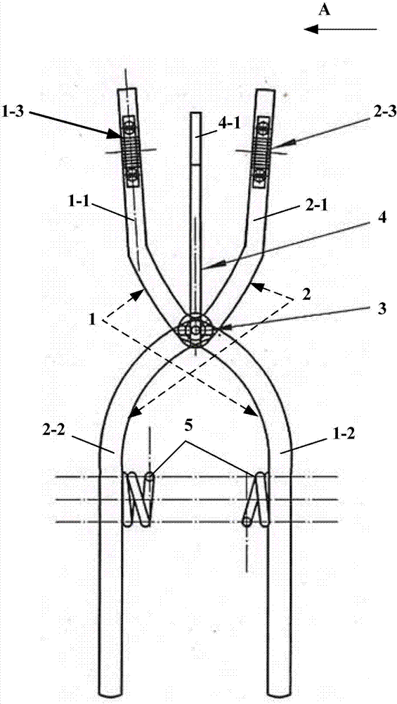
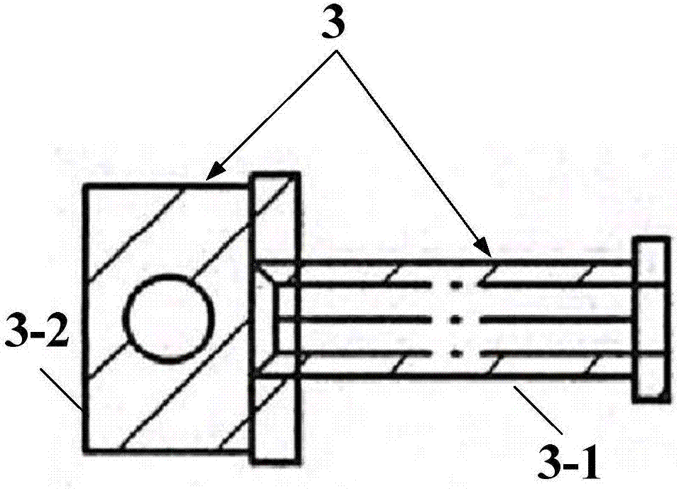
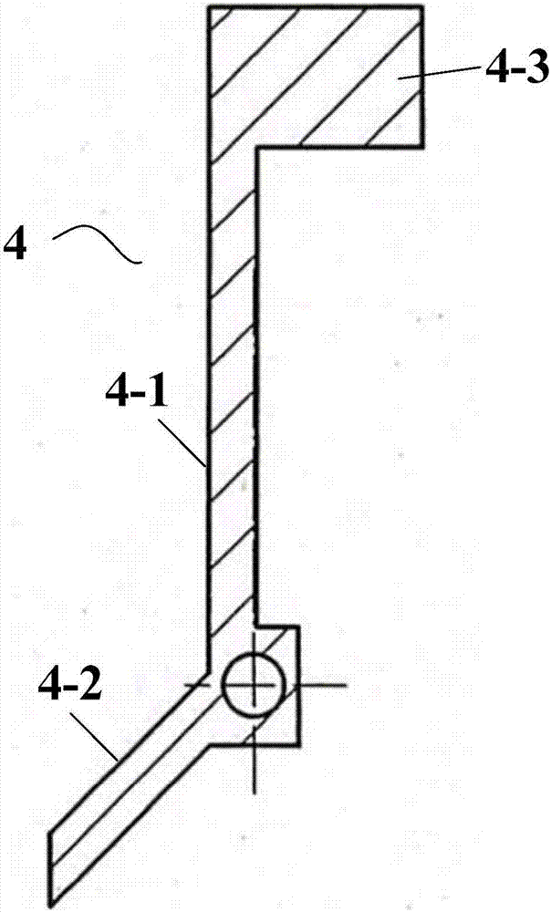
The invention provides a fixing and bonding device for a swing plate belt of a commercial rotary form printing machine. The fixing and bonding device comprises a first forceps arm, a second forceps arm, a connecting piece, a heating component and a compression spring; a first clamping component is arranged on a first forceps head of the first forceps arm; a second clamping component is arranged on a second forceps head of the second forceps arm; the connecting piece comprises a columnar connecting part and a heating component fixing part that are fixedly connected together; the heating component comprises a connecting rod; one end of the connecting rod is fixedly connected with an electric porcelain sheet; the other end of the connecting rod is fixedly connected with a heating handle; the first clamping component is used for fixing one breakage end of a breakage part of the swing plate belt of the commercial rotary form printing machine; the second clamping component is used for fixing the other one breakage end of the breakage part of the swing plate belt of the commercial rotary form printing machine; the compression spring is connected with a first forceps handle and a second forceps handle; when the heating handle is in an initial position, the electric porcelain sheet is located between the first clamping component and the second clamping component; when the heating handle is in a pressed-down state, the connecting rod, together with the electric porcelain sheet, is lifted away the initial position.

Description

technical field [0001] The invention relates to the field of form printing machines, in particular to a fixed bonding device for a swing plate belt of a commercial rotary form printing machine. Background technique [0002] Gongyao Commercial Rotary Form Printing Machine's pendulum plate shaft is connected to the drive belt up and down, and the belt is often broken. Because the belt is in a special position, it is difficult to re-bond it. The bonded finished belt cannot be installed, and can only be bonded at the original position of the machine. The traditional bonding method requires two people to cooperate. One person puts the two ends of the belt, and the other uses a soldering iron to melt the belt. The traditional bonding method is that the operating space is very narrow, and it is difficult to put the hands in the right position. Two people are needed. Cooperating with the operation, the second is that it is difficult to control the bonding strength, the bonding poin...

Claims


Application Information

Patent Timeline
IPC IPC(8): B29C65/18B29C65/78B29L29/00
CPCB29C65/18B29C65/7841B29C66/43B29L2029/00
Inventor 张健常洪波鲍志江
Owner 黑龙江省国家税务局票证站
Learn More