A three-dimensional puncture locating system

A positioning system and three-dimensional technology, applied in puncture needles, surgery, trocars, etc., can solve the problems of residual lethal rays, affecting the diagnosis of other patients, and high frequency of use in hospitals

Inactive Publication Date: 2017-07-28
青岛东海生命科技有限公司
View PDF6 Cites 6 Cited by
  • Summary
  • Abstract
  • Description
  • Claims
  • Application Information

AI Technical Summary

Problems solved by technology

When performing puncture, a certain depth of puncture needs to be verified by CT scan, and the operator judges the angle of difference based on experience; moreover, the puncture needle is not fixed by a fixing device. Patient posture changes due to respiratory movement
Especially for lesions or puncture sites smaller than 2cm, it is more difficult. Due to the constraints of technical level and changes in breathing range, multiple scanning and positioning are often required, so that the patient will be killed by radiation multiple times, and the medical staff will go back and forth many times. The imaging equipment room is even more affected (scanning equipment is in a paused state, and there will still be residual lethal rays indoors)
Especially for the lesions close to the body surface, they cannot be fixed during puncture and positioning, so medical staff can only be used as supports, which not only damages the health of medical staff, but also wastes precious time, because CT and MRI are very expensive equipment , the frequency of use in the hospital is extremely high, and multiple positioning scans will also affect the diagnosis of other patients

Method used


Image

  • A three-dimensional puncture locating system
  • A three-dimensional puncture locating system
  • A three-dimensional puncture locating system

Examples


Embodiment Construction

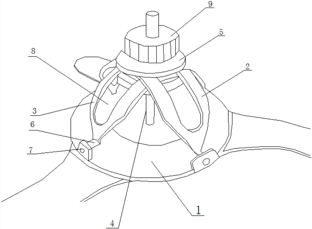
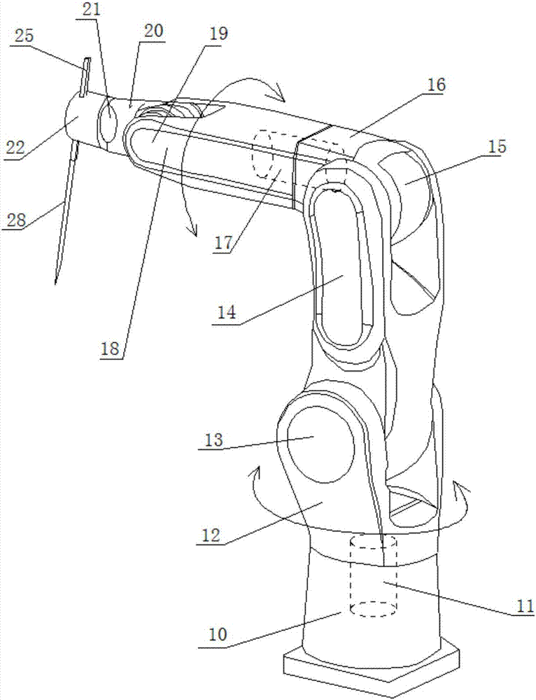
[0012] Such as figure 1 with Figure 4 As shown, the three-dimensional puncture positioning system of the present invention includes a bed board, a mechanical arm arranged on the bed board, and a body surface locator. The body surface locator includes a support sticker 1, a semicircular upper positioning ring 2, a lower positioning ring 3, The metal guide tube 4 and the slide table 5, the upper positioning ring 2, the lower positioning ring 3 and the support sticker 1 are movably connected, the two lower ends of the upper and lower positioning rings are provided with a protruding hinge shaft 6, and the corresponding positions of the support sticker 1 are provided with hinges. The ring 7, the upper positioning ring 2 and the lower positioning ring 3 are installed crosswise on the support sticker 1. The upper positioning ring 2 and the lower positioning ring are perpendicular to each other. It can slide along the slide rail 8. The metal guide tube 4 is installed on the slide ta...


PUM


Abstract

The invention relates to a three-dimensional puncture locating system comprising a bed plate, a mechanical arm arranged on the bed plate and a body surface locator, wherein the body surface locator comprises a support paste, a semi-spherical upper locating ring, a semi-spherical lower locating ring, a metal guide tube and a slide table. The upper locating ring and the lower locating ring are movably connected with the support paste; the upper locating ring and the lower locating ring are installed on the support paste in an intersecting manner; the upper and lower locating rings are provided with slide rails; the slide table can slide along the slide rails; the metal guide tube is arranged on the slide table which is also provided with a locking mechanism; when the locking mechanism is loosened, the slide table can slide along the slide rails, and when the locking mechanism is locked, the slide table cannot slide. The three-dimensional puncture locating system has the advantages that the body surface adjustable fixing device is provided, the metal guide tube is used for scanning guide, and human body parts or foci are accurately located and punctured according to extension lines; the mechanical arm is used for controlling a puncture needle or a curing instrument; dynamic location is achieved in a remote control manner or in a manual manner; through safe location of three points and one line, location, puncturing and treatment can be completed quickly.

Description

technical field [0001] The invention relates to a medical device, especially a puncture device. Background technique [0002] The puncture positioning technology in the imaging department has become an important standard for testing radiologists. The current CT-guided lung puncture biopsy is performed with bare hands. Because the positioning of the puncture biopsy in the three-dimensional space is very complicated and difficult, the current CT-guided lung biopsy is very complicated and difficult. Puncture is still limited to a two-dimensional plane, and the selection of puncture paths is limited. When performing a biopsy, the position of the puncture needle is not determined by quantitative data. The operator adjusts the direction of the puncture needle based on empirical observation of CT images. Repeated adjustments are required to achieve the correct puncture direction. When performing puncture, a certain depth of puncture needs to be verified by CT scan, and the operato...

Claims


Application Information

Patent Timeline
IPC IPC(8): A61B17/34A61B10/02
CPCA61B17/3403A61B10/02A61B2017/3407A61B2017/3409
Inventor 宓兵向云孙兵
Owner 青岛东海生命科技有限公司
Why Eureka
Try Eureka