Self-control type lifting device for electrical automation equipment

A technology of electrical automation and electrical equipment, applied in the direction of transportation and packaging, casters, wheels, etc., can solve the problems of not being able to use at any time, property loss and casualties, poor safety performance, etc., to achieve convenient and safe installation and operation , strong market application prospects, and the effect of protecting electrical equipment

Inactive Publication Date: 2017-07-28
赵博皓
View PDF5 Cites 1 Cited by
  • Summary
  • Abstract
  • Description
  • Claims
  • Application Information

AI Technical Summary

Problems solved by technology

[0002] Electrical automation equipment is a precision processing instrument, and it is a method of controlling mechanical movement and processing by using digital information. It is a large-scale processing machine that requires a large number of It is manually moved by the personnel, or it is moved and lifted by forklifts and cranes, but the mobile lifting device in the prior art has the following disadvantages when it acts on the equipment: 1. It is a precision instrument and should not appear Larger vibration, 2. When using traditional technology to move and lift, the safety performance is poor, which is easy to cause damage and damage to equipment, resulting in property loss and casualties. 3. Poor convenience and cannot be used at any time

Method used


Image

  • Self-control type lifting device for electrical automation equipment
  • Self-control type lifting device for electrical automation equipment
  • Self-control type lifting device for electrical automation equipment

Examples


Embodiment Construction

[0018] The following will clearly and completely describe the technical solutions in the embodiments of the present invention with reference to the accompanying drawings in the embodiments of the present invention. Obviously, the described embodiments are only some, not all, embodiments of the present invention. Based on the embodiments of the present invention, all other embodiments obtained by persons of ordinary skill in the art without making creative efforts belong to the protection scope of the present invention.

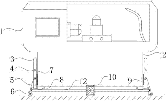
[0019] see Figure 1-6 , the present invention provides a technical solution: a self-controlled lifting device for electrical automation equipment, comprising an electrical equipment body 1 and a base 2, the base 2 is provided with the lower end of the electrical equipment body 1, and the four corners of the bottom end of the base 2 are provided with feet. And there is a gap between the side wall of the base 2 and the ground.

[0020] A supporting structure 8...


PUM


Abstract

The invention relates to the technical field of electrical automation, and particularly to a self-control type lifting device for electrical automation equipment. The lifting device comprises an electrical equipment body and a base, the base is arranged at the lower end of the electrical equipment body, the upper end face of a support structure is in contact with the bottom end face of the side wall of the electrical equipment body, a plurality of sets of vertical plates are arranged at the upper end of a mounting plate, the top ends of the vertical plates are all fixedly connected with the lower end of a connection rod, an air pressure power assembly comprises a telescopic cylinder, a driven rod, a hinge, a power rod assembly and a power rod, the power rod assembly comprises two power rods and a support shaft, sliding wheels are connected with both the two side walls of the driven rod, and the inner side face of the hinge is in contact with the surfaces of the sliding wheels. The self-control type lifting device for the electrical automation equipment can achieve movement through a reasonable structure, great vibration is avoided, safe ground getting off can be achieved, the phenomenon of breaking of a damaged machine does not exist, and structures are connected reasonably to achieve removable installation.

Description

technical field [0001] The invention relates to the technical field of numerical control machinery, in particular to a self-controlled lifting device for electrical automation equipment. Background technique [0002] Electrical automation equipment is a precision processing instrument, and it is a method of controlling mechanical movement and processing by using digital information. It is a large-scale processing machine that requires a large number of It is manually moved by the personnel, or it is moved and lifted by forklifts and cranes, but the mobile lifting device in the prior art has the following disadvantages when it acts on the equipment: 1. It is a precision instrument and should not appear Larger vibration, 2. When using traditional technology to move and lift, the safety performance is poor, and it is easy to cause equipment damage and damage, resulting in property loss and casualties. 3. The convenience is poor, and it cannot be used at any time. Contents of ...

Claims


Application Information

Patent Timeline
Patent Type & Authority Applications(China)
IPC IPC(8): B60B33/06
CPCB60B33/066
Inventor 赵博皓赵博文
Owner 赵博皓
Why Eureka
Try Eureka