Inverted electrolytic polishing device and electrolytic polishing equipment thereof

An electrolytic polishing and inversion technology, applied in the direction of electrolytic process, electrolytic components, etc., can solve problems such as poor effect, poor electrolysis of stainless steel containers, and low production efficiency, so as to improve the degree of automation and production efficiency, and realize the degree of infiltration and contact , the effect of preventing air bubbles

Active Publication Date: 2017-07-28
无锡市鹏振智能科技有限公司
View PDF6 Cites 12 Cited by
  • Summary
  • Abstract
  • Description
  • Claims
  • Application Information

AI Technical Summary

Problems solved by technology

If there are air bubbles, there will be defects of poor electrolysis on the inner wall surface of the electropolished stainless steel container, that is, "white spots"
As a result, the electrolytic polishing device or production equipment in the prior art has a poor effect on the electrolytic polishing of the inner wall surface of the stainless steel container
At the same time, the electrolytic polishing equipment in the prior art also has the defects of poor automation and low production efficiency.

Method used


Image

  • Inverted electrolytic polishing device and electrolytic polishing equipment thereof
  • Inverted electrolytic polishing device and electrolytic polishing equipment thereof
  • Inverted electrolytic polishing device and electrolytic polishing equipment thereof

Examples


Embodiment 1

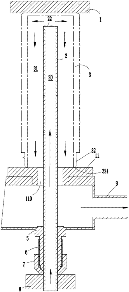
[0031] ginseng figure 1 , Figure 4 and Figure 5 The first specific implementation of an inverted electrolytic polishing device is shown.

[0032] In this embodiment, the workpiece 3 is inverted and extended into the inner cavity 31 of the workpiece 3 through the electrolytic rod 2 , and the electrolyte 81 is injected. Electrolyte 81 ginseng figure 1 In the direction shown by the middle arrow, it flows through the columnar channel 20 formed by the electrolytic rod 2 in a bottom-up manner, and flows out of the electrolytic rod 2 from the opening 22 at the top, and finally fills the workpiece 3 Internal cavity 31 .

[0033] During electropolishing, the workpiece 3 is located between the anode 1 and the cathode 8 . The anode 1 can be moved up and down by the electrode lifting mechanism 40 as a whole, so that both ends of the workpiece 3 are clamped by the anode 1 and the cathode 8 respectively. It should be noted that, in this application, the workpiece 3 is a cup-shaped o...

Embodiment 2

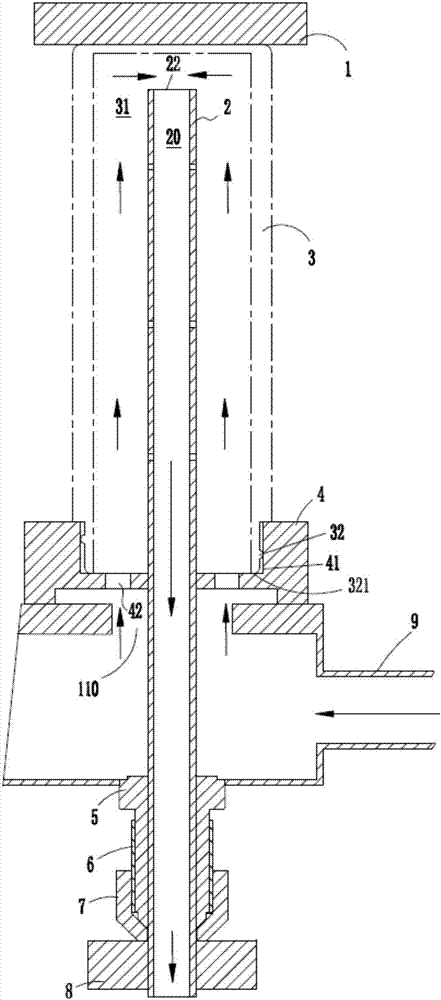
[0042] ginseng image 3 , Figure 4 and Figure 5 The second specific implementation of an inverted electrolytic polishing device is shown.

[0043] The main difference between this embodiment and the inverted electrolytic polishing device disclosed in Embodiment 1 is that, in this embodiment, a number of injection holes 21 are opened on the side wall of the electrolytic rod 2 . At the same time, the electrolytic rod 2 in this embodiment can be linear or spiral, and a number of injection holes 21 are provided on the side wall of the electrolytic rod 2 .

[0044] In this embodiment, the function of the spray hole 21 is: when the electrolyte 81 flows upward in the columnar channel 20 formed by the electrolytic rod 2, part of the electrolyte 81 can be sprayed horizontally, so that the horizontal The electrolyte solution 81 sprayed in a circular shape strips off the remaining air bubbles attached to the inner wall surface of the workpiece 3, and takes away from the inner cavity...

Embodiment 3

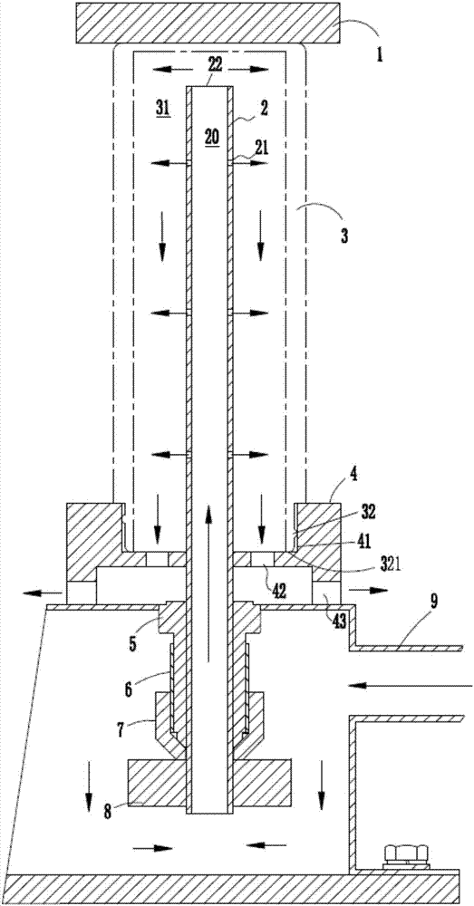
[0047] ginseng figure 2 , Figure 4 and Figure 5 The third embodiment of an inverted electrolytic polishing device is shown.

[0048] The main difference between this embodiment and the inverted electrolytic polishing device disclosed in Embodiment 1 and Embodiment 2 is that, in this embodiment, a disc-shaped support 4 is provided between the mouth 32 of the workpiece 3 and the return pipe 9 A plurality of first through holes 42 are provided along the longitudinal direction of the bracket 4 , and the first through holes 42 are used to establish a circulation path between the internal cavity 31 of the workpiece 3 and the return pipe 9 .

[0049] Specifically, see figure 2 As shown, in this embodiment, the bracket 4 is in the shape of a disc, and a circular concave portion 41 is formed on the top of the bracket 4, and the mouth 32 of the workpiece is accommodated and clamped by the concave portion 41. The bottom surface of the ring formed by the bottom edge 321 of the mou...


PUM


Abstract

The invention provides an inverted electrolytic polishing device and electrolytic polishing equipment thereof. The inverted electrolytic polishing device comprises an electrolytic bath, a plurality of electrolytic bars perpendicularly arranged in the electrolytic bath, an anode and / or a cathode infiltrated by electrolytic solutions circularly flowing in the electrolytic bath, and a backflow pipe. The electrolytic bars are hollow, two ends of each electrolytic bar extend into a workpiece and the backflow pipe respectively, the workpieces are located between the anode and the cathode and communicate with the backflow pipe through openings of the workpieces, and the openings of the workpieces are arranged downwards. The inverted electrolytic polishing device and the electrolytic polishing equipment have the advantages that the workpieces are placed upside down and the electrolytic solutions are injected upwards through the hollow electrolytic bars, so that the infiltration and contact degree of inner wall surfaces of the workpieces and the electrolytic solutions are achieved, the situation that bubbles occur when the inner wall surfaces are subjected to electrolytic polishing is effectively prevented, the electrolytic polishing effect is improved, and the automation degree and production efficiency of electrolytic polishing are improved.

Description

technical field [0001] The invention relates to the technical field of metal surface treatment, in particular to an inverted electrolytic polishing device and an electrolytic polishing device thereof. Background technique [0002] Electropolishing is a method of finishing the surface of a metal workpiece. The method is to place the metal workpiece in an electrolytic polishing tank filled with electrolytic polishing liquid, and energize the electrolytic polishing liquid for electrolysis. As the electrolysis proceeds, a liquid film with high viscosity is formed on the surface of the metal workpiece. The thickness distribution of the liquid film on the uneven surface of the metal workpiece is uneven. The liquid film on the surface of the convex part is thin, while the liquid film on the surface of the rest Thick, so the resistance of the anode surface is not the same everywhere. The raised part of the metal workpiece has low resistance and high current density, which makes the...

Claims


Application Information

Patent Timeline
Patent Type & Authority Applications(China)
IPC IPC(8): C25F3/16C25F7/00
CPCC25F3/16C25F7/00
Inventor 徐春奇
Owner 无锡市鹏振智能科技有限公司
Why Eureka
Try Eureka