A method and device for controlling a fuel metering system of an internal combustion engine

A technology of internal combustion engine and fuel, applied in the direction of electrical control, engine control, fuel injection control, etc., can solve the problem of not optimal fuel consumption, and achieve the effect of energy saving

Active Publication Date: 2017-07-28
ROBERT BOSCH GMBH
View PDF11 Cites 0 Cited by
  • Summary
  • Abstract
  • Description
  • Claims
  • Application Information

AI Technical Summary

Problems solved by technology

In mass production, this leads to overly increased preload values ​​on average
Since the generation of the low pressure by the delivery pump requires energy from the on-board electrical system, this method is not optimal for the fuel consumption of the vehicle due to tolerance tolerances.

Method used


Image

  • A method and device for controlling a fuel metering system of an internal combustion engine
  • A method and device for controlling a fuel metering system of an internal combustion engine
  • A method and device for controlling a fuel metering system of an internal combustion engine

Examples


Embodiment Construction

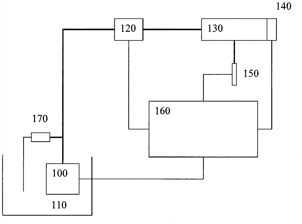
[0016] in figure 1 The basic elements of the fuel distribution system (Kraftstoffzumesssystem) are shown in. in figure 1 The Förderpumpe is marked with 100. The delivery pump delivers fuel from the storage tank 110 to the high-pressure pump 120. The high-pressure pump 120 builds up pressure in the high-pressure area. In particular, the high-pressure region includes a pressure accumulator (Druckspeicher), which is also referred to as a “rail” (Rail) 130. In addition, a pressure sensor 140 is arranged in the high pressure area. From the rail 130, fuel enters the combustion chamber of the internal combustion engine through the injector 150. The pressure build-up (the pressure build-up is performed by the opening and closing of the high-pressure pump 120, the ejector 150, and the power output of the delivery pump 100) is controlled by the control device 160. This control device 160 also analyzes the output signal of the pressure sensor 140.

[0017] The area between the delivery...


PUM


Abstract

The invention relates to a method for controlling a fuel metering system of an internal combustion engine, wherein the fuel metering system comprises a delivery pump and a high-pressure pump, the control signal of the delivery pump is increased at the start of the internal combustion engine and is acquired, and a pressure-limiting valve makes a response to the control signal.

Description

Technical field [0001] The invention starts from the device and method according to the preamble of the independent claim. Background technique [0002] DE 198 53 823 A1 discloses a method for operating a fuel distribution system of an internal combustion engine. The fuel distribution system includes a delivery pump and a high-pressure pump. The delivery pump delivers fuel from the fuel storage tank (Vorratsbehälter) through the low-pressure area to the high-pressure pump. The high-pressure pump delivers fuel into the high-pressure area, which in particular includes so-called rails. From the rail, fuel reaches the injectors of the individual combustion chambers of the internal combustion engine. [0003] For the systems currently used in mass production, the fuel distribution system consists of a low-pressure system and a high-pressure system. Here, it is preferable to use a pre-controlled low-pressure system, which must be sufficient if there is no pressure sensor in the low-p...

Claims


Application Information

Patent Timeline
Patent Type & Authority Applications(China)
IPC IPC(8): F02D41/30F02D41/14
CPCF02D41/1401F02D41/3082F02D41/062F02D41/2438F02D41/3863F02D2200/0602
Inventor A.S.Z.施魏因斯贝格B.希勒H-F.施瓦茨J.金佩尔K.约斯
Owner ROBERT BOSCH GMBH
Why Eureka
Try Eureka