LED filament lamp with gas dissipation function and machining process of LED filament lamp

A LED filament lamp and LED filament technology, applied in lighting and heating equipment, semiconductor devices of light-emitting elements, cooling/heating devices of lighting devices, etc., can solve the problem of unfavorable heat dissipation of LED filaments, high temperature of LED filaments, and short service life of products and other issues, to achieve the effect of increasing heat dissipation, good heat dissipation performance, and increasing thermal conductivity

Active Publication Date: 2017-07-28
浙江金陵光源电器有限公司
View PDF5 Cites 5 Cited by
  • Summary
  • Abstract
  • Description
  • Claims
  • Application Information

AI Technical Summary

Problems solved by technology

[0003] LED filament lighting has the effect of traditional tungsten lamps. LED filaments will generate a lot of heat, but because the main body of LED filaments is suspended in the air, the thermal conductivity of the air is only 0.026W / m*K, which is not conducive to the heat dissipation of LED filaments, resulting in LED filaments The temperature is very high, resulting in serious light decay and short service life of the product
Among all gases, the thermal conductivity of hydrogen is the largest, and its thermal conductivity is 0.163 W / m*K and 0.224 W / m*K at 0°C and 100°C, respectively, while helium is next. At 0°C and 100°C, the thermal conductivity coefficients are 0.144 W / m*K and 0.175 W / m*K respectively, and the mixture of hydrogen and oxygen is easy to explode; experiments have proved that the optimum pressure of helium in the filament lamp is 1.1 atmospheres, while the current Due to technical limitations, the production process can only fill the bulb with a gas of 0.98 atmospheres, and it is worried that filling hydrogen will cause combustion and explosion. At present, only pure helium can be filled.

Method used


Image

  • LED filament lamp with gas dissipation function and machining process of LED filament lamp

Examples


Embodiment Construction

[0017] The present invention will be described in further detail below in conjunction with the accompanying drawings, but it should not be understood that the scope of the above-mentioned theme of the present invention is limited to the above-mentioned embodiments.

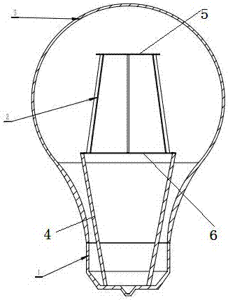
[0018] A gas-radiated LED filament lamp, comprising a lamp base 1, an LED filament 2 and a bulb 3, the lamp base 1 and the bulb 3 form a sealed space, and an upper bracket 5, an LED filament 2 and a lower bracket are arranged in the sealed space from top to bottom 6. The upper bracket 5 and the lower bracket 6 are used to fix the LED filament 2. The LED filament 2 is connected to the driving circuit through the wire 4, and the closed space is filled with a mixed gas of hydrogen, helium and air at 1.1 atmospheres, of which the volume of hydrogen occupies The proportion of helium is 6~10%, and the proportion of helium is 90~96%. A large number of experiments have proved that the mixed gas of this component has the b...


PUM


Abstract

The invention relates to lighting products, in particular to an LED filament lamp and discloses an LED filament lamp with a gas dissipation function. The LED filament lamp with the gas dissipation function comprises a lamp cap, an LED filament and a bulb. A sealed space is defined by the lamp cap and the bulb. An upper support, the LED filament and a lower support are arranged in the sealed space from top to bottom. The upper support and the lower support are used for fixing the LED filament which is connected with a drive circuit through a wire. The sealed space is filled with mixed gas of 1.1 atmospheric pressures, and the mixed gas is a mixture of hydrogen with the volume ratio being 6-10% and helium with the volume ratio being 90-94%. A mass of experiments prove that the mixed gas with such constituents has the optimal heat dissipation performance, and meanwhile, burning or explosions are avoided. Compared with a traditional LED filament lamps filled with helium only, the 10-W LED filament lamp adopting the proportions has the advantages that the LED junction temperature is lowered by 5-8 DEG C, the service life of the LED filament lamp is substantially prolonged, and light output is substantially improved.

Description

technical field [0001] The invention relates to lighting products, in particular to an LED filament lamp. [0002] The invention relates to an LED lamp processing technology, in particular to an LED filament lamp processing technology. Background technique [0003] LED filament lighting has the effect of traditional tungsten lamps. LED filaments will generate a lot of heat, but because the main body of LED filaments is suspended in the air, the thermal conductivity of the air is only 0.026W / m*K, which is not conducive to the heat dissipation of LED filaments, resulting in LED filaments The temperature is very high, resulting in serious light decay and short service life of the product. Among all gases, the thermal conductivity of hydrogen is the largest, and its thermal conductivity is 0.163 W / m*K and 0.224 W / m*K at 0°C and 100°C, respectively, while helium is next. At 0°C and 100°C, the thermal conductivity coefficients are 0.144 W / m*K and 0.175 W / m*K respectively, and th...

Claims


Application Information

Patent Timeline
Patent Type & Authority Applications(China)
IPC IPC(8): F21K9/232F21V29/503F21V29/85F21K9/90F21Y115/10
CPCF21K9/90F21V29/503F21V29/85
Inventor 应智章乔振中
Owner 浙江金陵光源电器有限公司
Why Eureka
Try Eureka