Flat wire type dynamic elasticity electric conducting system

A dynamic elastic, linear technology, applied in circuit layout, lighting device, lighting device components, etc., can solve problems such as unreliable performance, limited travel of barrel and tail cover, poor conductive contact, etc.

Inactive Publication Date: 2017-07-28
XENO CO SHANGLUO LTD
View PDF8 Cites 0 Cited by
  • Summary
  • Abstract
  • Description
  • Claims
  • Application Information

AI Technical Summary

Problems solved by technology

Both conductive structures have the problem of poor conductive contact. Now there are parts similar to shrapnel added between the barrel body and the tail cover of the lighting device to achieve a dynamic conductive effect, but there is a limited travel between the barrel body and the tail cover and Issues such as unreliable performance when used for a long time

Method used


Image

  • Flat wire type dynamic elasticity electric conducting system
  • Flat wire type dynamic elasticity electric conducting system
  • Flat wire type dynamic elasticity electric conducting system

Examples


Embodiment Construction

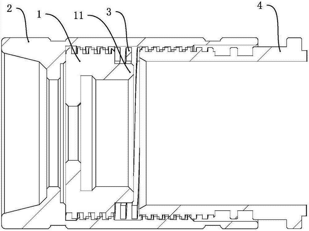
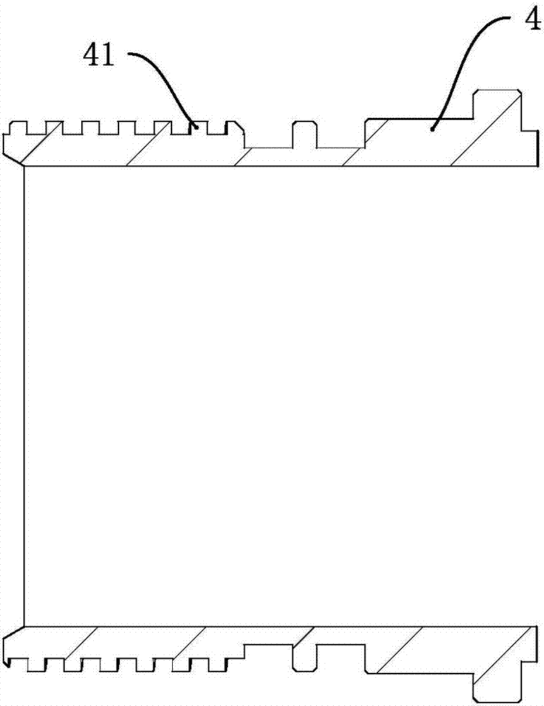
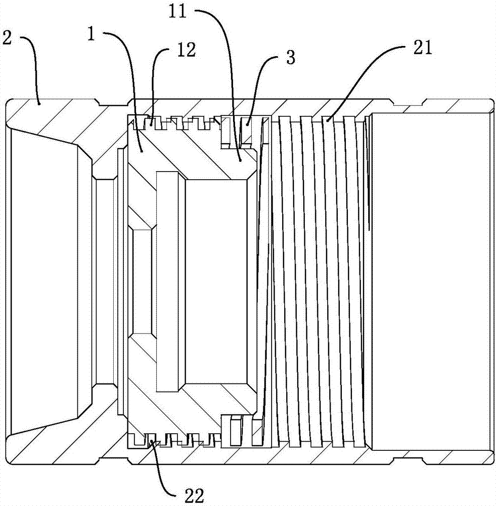
[0014] Such as Figure 1 to Figure 3 As shown, a flat wire type dynamic elastic conductive system includes a cylinder body 4, a tail cap 2 provided with an accommodating cavity, a switch frame 1 and a flat wire spring 3, the cylinder body 4 is provided with a first external thread 41, and the tail cap 2 There is a first internal thread 21 and the first internal thread 21 is close to the opening end of the tail cap 2, the switch frame 1 is set in the accommodating cavity and the switch frame 1 is in contact with the inner wall of the tail cap 2, the first external thread of the cylinder body 4 End 41 extends into the tail cap 2 and is threadedly connected with the tail cap 2. One end of the flat wire spring 3 abuts against the switch frame 1, and the other end abuts against the end surface of the cylinder body 4.

[0015] Such as Figure 1 to Figure 3 As shown, when the cylinder body 4 and the tail cap 2 are tightened, the end surface of the cylinder body 4 is pressed against ...


PUM


Abstract

The invention discloses a flat wire type dynamic elasticity electric conducting system. The flat wire type dynamic elasticity electric conducting system comprises a cylinder, a tail cover provided with an accommodating cavity, a switch bracket and a flat wire spring, wherein the cylinder is provided with first external threads; the tail cover is provided with first internal threads, and the first internal threads are close to the opening end of the tail cover; the switch bracket is arranged in the accommodating cavity, and the switch bracket is in contact with the inner wall of the tail cover; the first external threads of the cylinder extend into the tail cover and are in thread connection with the tail cover; and one end of the flat wire spring is pressed against the switch bracket, and the other end of the flat wire spring is pressed against the end surface of the cylinder. The flat wire type dynamic elasticity electric conducting system has the advantages that in the process of tightening or loosening the cylinder and the tail cover, as the switch bracket comes into great contact with the end surface of the cylinder under the elasticity action of the flat wire spring, the problem that the contact of the switch bracket and the end surface of the cylinder is poor due to the too-large rotating stroke of the cylinder and the tail cover can be solved.

Description

technical field [0001] The invention relates to the technical field of lighting, in particular to a flat-line dynamic elastic conductive system. Background technique [0002] The conductive structure of the existing lighting device can be roughly divided into two types, the thread conduction and the end face conduction. Both conductive structures have the problem of poor conductive contact. Now there are parts similar to shrapnel added between the barrel body and the tail cover of the lighting device to achieve a dynamic conductive effect, but there is a limited travel between the barrel body and the tail cover and Problems such as unreliable performance when used for a long time. Contents of the invention [0003] The purpose of the present invention is to solve the deficiencies of the prior art and provide a flat wire type dynamic elastic conductive system. [0004] A kind of technical scheme of the present invention: [0005] A flat wire type dynamic elastic conducti...

Claims


Application Information

Patent Timeline
Patent Type & Authority Applications(China)
IPC IPC(8): F21V23/06F21V17/12F21V17/16
CPCF21V17/12F21V17/162F21V23/06
Inventor 刘珺陈光涛
Owner XENO CO SHANGLUO LTD
Why Eureka
Try Eureka