
Power and bandwidth combined distribution method used for target tracking with networking radar system

A networked radar and joint distribution technology, which is applied in the radio wave measurement system, using re-radiation, radio wave reflection/re-radiation, etc., can solve problems such as large amount of calculation, poor tracking performance, and failure to obtain optimal solutions , to achieve the effect of improving tracking accuracy, low computation load, and satisfying real-time performance

Active Publication Date: 2017-07-28
西安彼睿电子科技有限公司
View PDF4 Cites 20 Cited by
  • Summary
  • Abstract
  • Description
  • Claims
  • Application Information

AI Technical Summary

Problems solved by technology

However, this paper regards power allocation as a non-convex optimization problem and uses a greedy algorithm to solve it, but the greedy algorithm has a large amount of calculation and may not obtain the optimal solution
[0005] Xidian University disclosed a multi-beam transmission power dynamic allocation method for radar multi-target tracking in its patent application (patent application number: 201110260636.6, publication number: 102426358A). The dynamic allocation method of beam transmission power solves the problem of poor tracking performance when a single radar station performs multi-target tracking, but this method cannot be applied in traditional networked radar systems

Method used


Image

  • Power and bandwidth combined distribution method used for target tracking with networking radar system
  • Power and bandwidth combined distribution method used for target tracking with networking radar system
  • Power and bandwidth combined distribution method used for target tracking with networking radar system

Examples


Embodiment Construction

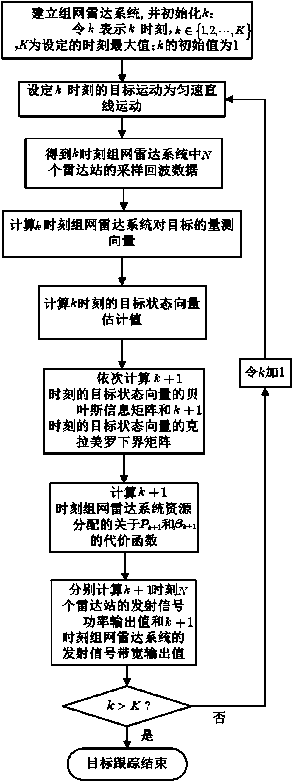
[0033] refer to figure 1 , is a flow chart of a method for jointly allocating power and bandwidth of a networked radar system for target tracking of the present invention; wherein the method for jointly allocating power and bandwidth of a networked radar system for target tracking includes the following steps:

[0034]Step 1, establish a networked radar system, the networked radar system includes a fusion center and N radar stations, and there are targets in the detection areas of the N radar stations; N radar stations transmit signals to targets in their detection areas and receive Echo data, the echo data includes the radial distance of the target relative to each radar station, and the Doppler frequency shift of the target relative to each radar station; N radar stations send the received echo data To the fusion center for fusion processing, the fusion center estimates the state of the target according to the echo data, and then obtains the transmit signal power output valu...


PUM


Abstract

The invention discloses a power and bandwidth combined distribution method used for target tracking with a networking radar system. The method comprises steps of establishing the networking radar system, wherein the networking radar system comprises a fusion center and N radar stations and targets exist in detection regions of the N radar stations; initializing k, where k belongs to {1, 2, ..., K}, calculating sampling echo data of the N radar stations in the networking radar system at the moment of k, and sending the sampling echo data to the fusion center; after receiving echo data waveforms reflected by the targets received by the N radar stations in the networking radar system at the moment of k through the fusion center, calculating target state vector estimation values at the moment of k, calculating cost functions about Pk+1 and betak+1 of resource distribution of the networking radar system at the moment of k+1, and calculating emission signal power output values of the N radar stations at the moment of k+1 and emission signal bandwidth output values of the networking radar system at the moment of k+1; and stopping tracking of the targets until the emission signal power output values of the N radar stations at the moment of k+1 and the emission signal bandwidth output values of the networking radar system at the moment of k+1 are obtained.

Description

technical field [0001] The invention belongs to the technical field of radar signal processing, and particularly relates to a method for jointly allocating power and bandwidth of a networked radar system for target tracking, which is suitable for effectively improving the utilization efficiency of limited transmission resources of a ship-borne or vehicle-mounted networked radar platform, and can Improve the tracking accuracy of the target. Background technique [0002] In recent years, with the development of science and technology and weaponry, it has been difficult for a single radar station to cope with increasingly complex combat environments. The use of traditional networked radar systems can effectively make up for the lack of single radar stations for target detection and tracking. Based on the network The target positioning and tracking accuracy of the radar system is related to many factors such as the number of radar stations and the transmitting signal power of ea...

Claims


Application Information

Patent Timeline
Patent Type & Authority Applications(China)
IPC IPC(8): G01S7/41G01S13/66
CPCG01S7/41G01S13/66
Inventor 严俊坤陈林刘宏伟纠博周生华
Owner 西安彼睿电子科技有限公司
Learn More