Optical receiving device and equipment

A light receiving and equipment technology, applied in electromagnetic receivers, television systems adapted to optical transmission, cable transmission adaptation, etc., can solve the problems of inability to check equipment, time-consuming and laborious, and achieve the effect of convenient installation and maintenance, and simplified connection.

Active Publication Date: 2017-07-28
华数传媒网络有限公司 +1
View PDF14 Cites 0 Cited by
  • Summary
  • Abstract
  • Description
  • Claims
  • Application Information

AI Technical Summary

Problems solved by technology

However, especially when using this device for IP data signal transmission, there are still many deficiencies in the actual use of this packaged product. It is time-consuming and labor-intensive to check the faulty equipment. It is necessary to open the case first.

Method used


Image

  • Optical receiving device and equipment
  • Optical receiving device and equipment
  • Optical receiving device and equipment

Examples


Embodiment 1

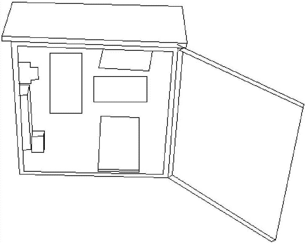
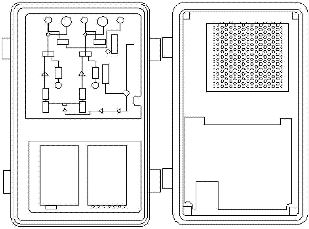
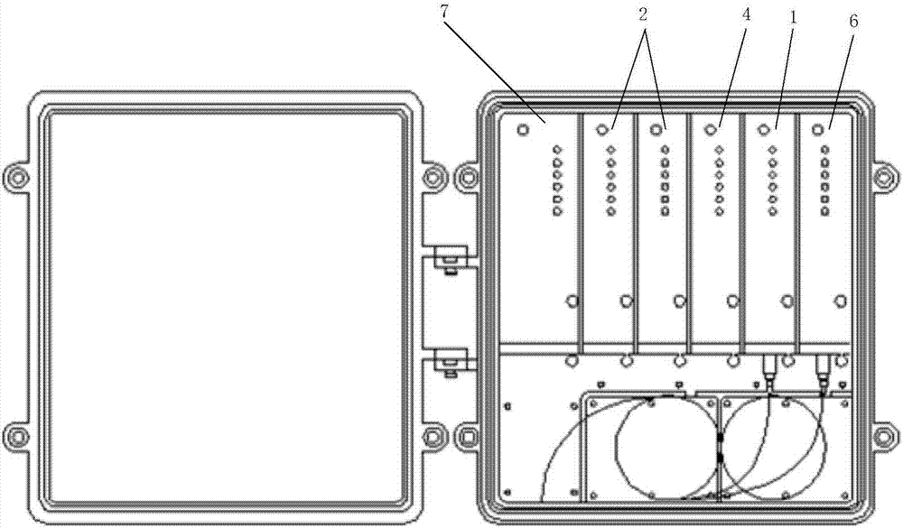
[0046] See image 3 , Figure 4 with Image 6 The optical receiving device proposed in this embodiment includes: a separate ONU module 1, an EOC module 2, a backplane connection module 3, and a switch management module 4. The ONU module 1 and EOC module 2 are connected to each other through the backplane connection module 3. The switch management module 4 is pluggable and connected, and the switch management module 4 and the ONU module 1 are set independently, which can ensure that the functions of each module are independent. The above-mentioned modules are all encapsulated in a field-type case. The field-type case is mostly a metal case, and the outer side of the metal case is coated with insulating and waterproof materials, so that the case can have good insulation and waterproof effects, and guarantee The power safety of each module is improved. The die-casting material used for the metal shell must meet the requirements of (die-cast aluminum alloy) GB / T15115-2009. The she...

Embodiment 2

[0053] See image 3 , Figure 5 with Image 6 The optical receiving equipment provided in this embodiment includes: a separate EOC module 2, a backplane connection module 3, and a switch management module 4. In the optical receiving equipment, the switch management module 4 integrates an ONU device 5. The switch management module 4 integrates the ONU module 1, which can effectively save installation space while ensuring the function of the module. The EOC module 2 is pluggable and connected to the switch management module 4 through the backplane connection module 3, each of the above-mentioned modules are encapsulated in a field-type chassis, and the field-type chassis is mostly a metal shell, and the outside of the metal shell is coated with insulation Materials and waterproof materials, so that the chassis has a good insulation effect and waterproof effect, to ensure the safety of electricity use of each module. The die-casting material used for the metal shell must meet the...


PUM


Abstract

The invention relates to the technical field of circuit designing, and provides an optical receiving device and equipment. The optical receiving device comprises an ONU module, EOC modules, a back panel connection module and a switching management module which are separately arranged, wherein the ONU module and the EOC modules are all connected with the switching management module in a pluggable manner through the back panel connection module; the ONU module carries out photoelectric conversion on IP data signals, and sends IP data signals obtained through the photoelectric conversion to the switching management module; and then the EOC modules receive IP data signals obtained through integration of the switching management module, and carry out modulation / demodulation on the IP data signals. Therefore, connection among the equipment is effectively simplified, so that the equipment can be more conveniently mounted and maintained.

Description

Technical field [0001] The present invention relates to the technical field of circuit design, in particular to light receiving devices and equipment. Background technique [0002] With the development of science and technology and the improvement of people's living standards, radio and television and broadband networks have entered people's lives and work, and provide people with more and more abundant experiences. Generally, broadcast television broadcasts audio and image programs to the outside world through radio waves or wires. Through radio and television, people can not only view the latest news at home and abroad, but also relax and relax through radio and television entertainment programs. In addition to radio and television, the rise of broadband networks has also made people's lives more colorful. [0003] Before users use applications such as radio and television and broadband networks, they need to access related equipment such as ONU (Optical Network Unit) equipment...

Claims


Application Information

Patent Timeline
Patent Type & Authority Applications(China)
IPC IPC(8): H04B10/60H04B10/67H04N7/22
CPCH04B10/60H04B10/67H04N7/22
Inventor 陆忠强张军童永清陈琦
Owner 华数传媒网络有限公司
Why Eureka
Try Eureka