Textile cloth spray-drying system

A drying system and technology for textile fabrics, applied in textile and papermaking, textile material processing, textile material carrier processing, etc., can solve the problems of waste, uneven drying, poor drying effect of cloth, etc., and improve the utilization rate , reduce costs and save dyes

Inactive Publication Date: 2017-08-01
湖州南浔凯普纺织有限公司
View PDF0 Cites 8 Cited by
  • Summary
  • Abstract
  • Description
  • Claims
  • Application Information

AI Technical Summary

Problems solved by technology

[0002] At present, most of the dyeing cloth drying systems on the market use dyeing vats for dyeing. Dyeing different colors of cloth requires different color dyeing vats. The cost is high, and the waste water generated after dyeing the cloth is large, which seriously pollutes the environment; and each piece of cloth is consumed. A lot of dyes, a lot of dyes are discharged with waste water, the waste is serious, and the utilization rate of dyes is low; when dyeing cloth and drying, it is easily affected by the climate and the technical level of workers, the quality stability of the dyed cloth is not ideal, and the effect of dyeing cloth Poor; when the dyeing cloth drying system is drying the cloth, when the cloth enters the drying box, the hot air set under the drying box is blown to the cloth to dry the cloth. Due to the unstable direction of the wind, the cloth is somewhat The corners are not blown by the hot air, and the drying is uneven, so that the fabric is easily deformed when it is conveyed out of the drying box
Therefore, the existing dyeing cloth drying system not only has the problems of high cost, polluting the environment, low utilization rate and poor dyeing effect, but also has the problems of poor drying effect and easy deformation of the cloth

Method used


Image

  • Textile cloth spray-drying system
  • Textile cloth spray-drying system
  • Textile cloth spray-drying system

Examples


Embodiment Construction

[0018] The present invention will be further described below in conjunction with the accompanying drawings and embodiments, but not as a basis for limiting the present invention.

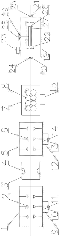
[0019] Example. A kind of textile cloth spray drying system, its composition is as follows Figures 1 to 3 As shown, including the dye box 1, the top surface and the bottom surface of the dye box 1 are respectively provided with a plurality of dye nozzles 2, and every 10 dye nozzles 2 form a row, and the top surface of the dye box 1 is provided with three rows, and the bottom surface is provided with three rows; One end of the dye box 1 is provided with a heating box 3; the other end of the heating box 3 corresponding to the dye box 1 is provided with a rinsing box 5; the bottom of the dye box 1 is connected with a dye filter 9, and a No. 1 filter screen 10 is arranged in the dye filter 9; The bottom of the dye filter 9 is provided with a No. water pump 11, and the No. 1 water pump 11 is connected ...


PUM


Abstract

The invention discloses a textile cloth spray-drying system, comprising a dye box (1); a plurality of dye nozzles (2) are arranged in the dye box (1); one end of the dye box (1) is provided with a heating box (3); the other end of the heating box (1) correspond to the dye box (1) is provided with a rinsing box (5); a dye filter (9) is connected below the bottom of the dye box (1); the other end of the rinsing box (5) corresponding to the heating box (3) is provided with a dewatering box (7); the other end of the dewatering box (7) corresponding to the rinsing box (5) is provided with a drying box (19); two cloth feeding rollers (20) and two cloth drawing rollers (21) are connected to two ends of the drying box (19) respectively; an electric heating plate (22) is arranged in the drying box (19); a controller (23) is arranged at the top end of the drying box (19). The textile cloth spray-drying system is good in dyeing uniformity, lower in cost, higher in dye utilization rate, and good in environment-protecting and dyeing effect, and also has the advantages of good cloth-drying effect and zero cloth deformation.

Description

technical field [0001] The invention relates to a textile cloth spraying and drying system applied in the textile industry. Background technique [0002] At present, most of the dyeing cloth drying systems on the market use dyeing vats for dyeing. Dyeing different colors of cloth requires different color dyeing vats. The cost is high, and the waste water generated after dyeing the cloth is large, which seriously pollutes the environment; and each piece of cloth is consumed. A lot of dyes, a lot of dyes are discharged with waste water, the waste is serious, and the utilization rate of dyes is low; when dyeing cloth and drying, it is easily affected by the climate and the technical level of workers, the quality stability of the dyed cloth is not ideal, and the effect of dyeing cloth Poor; when the dyeing cloth drying system is drying the cloth, when the cloth enters the drying box, the hot air set under the drying box is blown to the cloth to dry the cloth. Due to the unstable...

Claims


Application Information

Patent Timeline
Patent Type & Authority Applications(China)
IPC IPC(8): D06B21/00D06B1/02D06B23/20D06B15/02D06B19/00D06B15/04D06B15/00D06B23/04
CPCD06B21/00D06B1/02D06B15/00D06B15/02D06B15/04D06B19/007D06B23/04D06B23/20
Inventor 沈新荣周云芬
Owner 湖州南浔凯普纺织有限公司
Why Eureka
Try Eureka