Serpentine tube row, heat-exchanging device and layout method of serpentine tube row

A heat exchange device, serpentine tube technology, applied in heat exchange equipment, fixed tubular conduit components, heat exchanger types, etc., can solve the problems of small layout space requirements, poor heat transfer effect, designer obstacles, etc. The effect of reducing investment cost, saving layout space and high adaptability

Inactive Publication Date: 2017-08-01
SHANGHAI YINGUO THERMAL ENERGY EQUIP
View PDF0 Cites 1 Cited by
  • Summary
  • Abstract
  • Description
  • Claims
  • Application Information

AI Technical Summary

Problems solved by technology

Spiral finned tubes arranged in a staggered or parallel arrangement have the advantages of good heat transfer effect and small layout space requirements under the condition of choosing a base tube or finned tube material with a high thermal conductivity, but both will cause dust accumulation and clogging Until the wide application of H-type finned tubes, the phenomenon of dust accumulation and clogging can be improved, but the fly in the ointment is that due to the special shape of H-type finned tubes, they are generally arranged in line way, and the heat transfer effect of the arrangement of the heating surface in line is very inferior to that of the staggered arrangement. Moreover, due to the special shape of the H-shaped finned tubes, it is difficult to design and research the staggered arrangement. The majority of designers have created certain obstacles

Method used


Image

  • Serpentine tube row, heat-exchanging device and layout method of serpentine tube row
  • Serpentine tube row, heat-exchanging device and layout method of serpentine tube row
  • Serpentine tube row, heat-exchanging device and layout method of serpentine tube row

Examples


Embodiment Construction

[0039] The specific implementation manners of the present invention will be further described below in conjunction with the drawings and examples. The following examples are only used to illustrate the technical solution of the present invention more clearly, but not to limit the protection scope of the present invention.

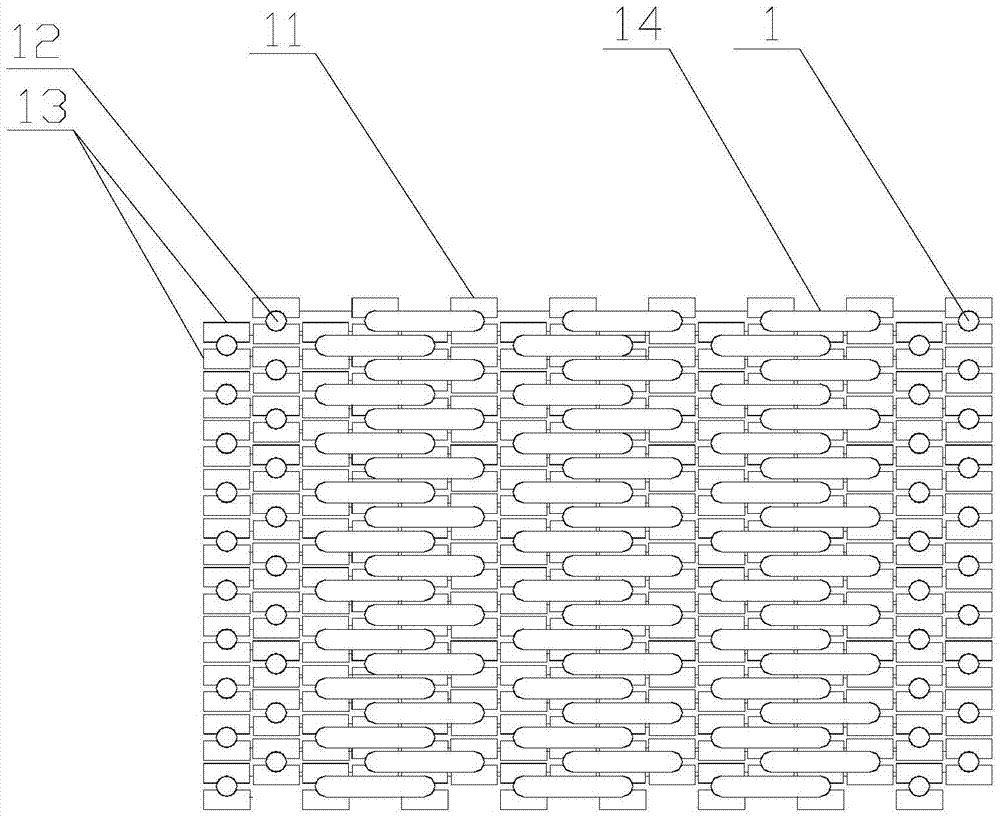
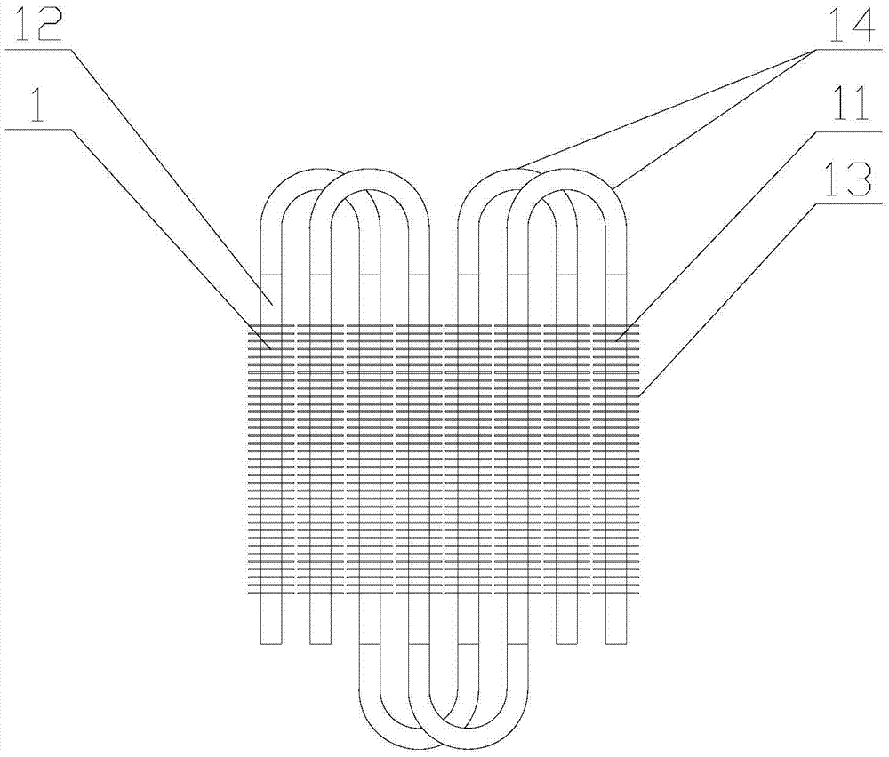
[0040] The present invention is a serpentine pipe row, such as figure 1 and figure 2 As shown, for heat exchange with the external fluid medium, the serpentine tube row includes several serpentine tubes 1; the serpentine tube 1 is composed of several finned tubes 11 connected end to end by several connecting elbows 14, and the fin The tube 11 includes a base tube 12 and fins 13; several serpentine tubes 1 are arranged parallel to each other along the radial direction of the base tube 12, and two adjacent base tubes 12 on the same serpentine tube 1 are arranged in a row .

[0041] Preferably, the fins 13 located in the same serpentine tube 1 are arranged...


PUM


Abstract

The invention discloses a serpentine tube row, a heat-exchanging device and a layout method of the serpentine tube row. The serpentine tube row is used for generating heat exchange with a fluid medium of the outside and comprises serpentine tubes, a framework fixedly connected with the serpentine tubes, an inlet tube reducer and an outlet tube reducer. The multiple serpentine tubes are arranged in a staggered mode in parallel, and every two adjacent base tubes located on the same serpentine tube are arranged in sequence. The framework comprises a left surface frame connected with the inlet tube reducer and a right surface frame connected with the outlet tube reducer. The fluid medium enters the framework through the inlet tube reducer and makes contact with the serpentine tube row, and then the fluid medium flows out through the outlet tube reducer. Every two adjacent base tubes located on the same serpentine tube are arranged in sequence. The multiple serpentine tubes are sequentially arranged in a staggered mode. The serpentine tube row, the heat-exchanging device and the layout method of the serpentine tube row have the advantages and beneficial effects that adaptability to the working environment is high, the heating area and the overall heat transfer coefficient of the heat-exchanging device are increased, the heat exchange efficiency is improved, the requirement for arrangement space is lowered, and cost of investment is reduced; and no adhesion or crossing exists between fins, and dust accumulation cannot happen easily.

Description

technical field [0001] The invention relates to the field of heat exchangers, in particular to a serpentine tube row, a heat exchange device and a method for arranging the serpentine tube row. Background technique [0002] Heat exchange is the heat transfer process between two objects or parts of the same object caused by temperature difference; and heat exchanger is used to transfer heat from hot fluid to cold fluid to meet the specified process requirements The device is an industrial application of convective heat transfer and heat conduction; [0003] At present, the heating surfaces of spiral finned tubes and H-shaped finned tubes are widely used in the field of heat exchangers or radiators, and there are two arrangements: staggered and parallel. Spiral finned tubes arranged in a staggered or parallel arrangement have the advantages of good heat transfer effect and small layout space requirements under the condition of choosing a base tube or finned tube material with ...

Claims


Application Information

Patent Timeline
Patent Type & Authority Applications(China)
IPC IPC(8): F28D7/08F28F9/00
CPCF28D7/082F28F9/001
Inventor 谢岩周群英
Owner SHANGHAI YINGUO THERMAL ENERGY EQUIP
Why Eureka
Try Eureka