Structure and manufacturing method of p-type crystalline silicon back-contact double-sided cell without front gate line
A front grid line, double-sided cell technology, applied in the field of solar cells, can solve the problem of leakage of MWT cells, which can not be solved well, reduce the production cost of cells, and have not been applied on a large scale, so as to prevent leakage and improve conversion. Efficiency, the effect of reducing production costs
- Summary
- Abstract
- Description
- Claims
- Application Information
AI Technical Summary
Problems solved by technology
Method used
Image
Examples
Embodiment 1
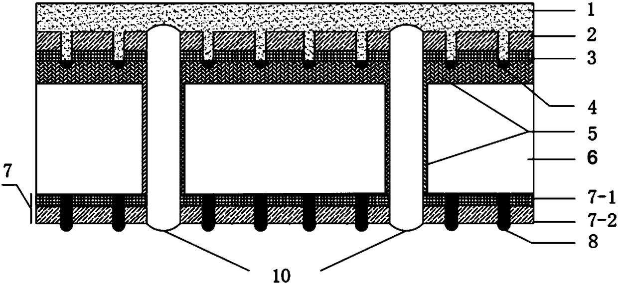
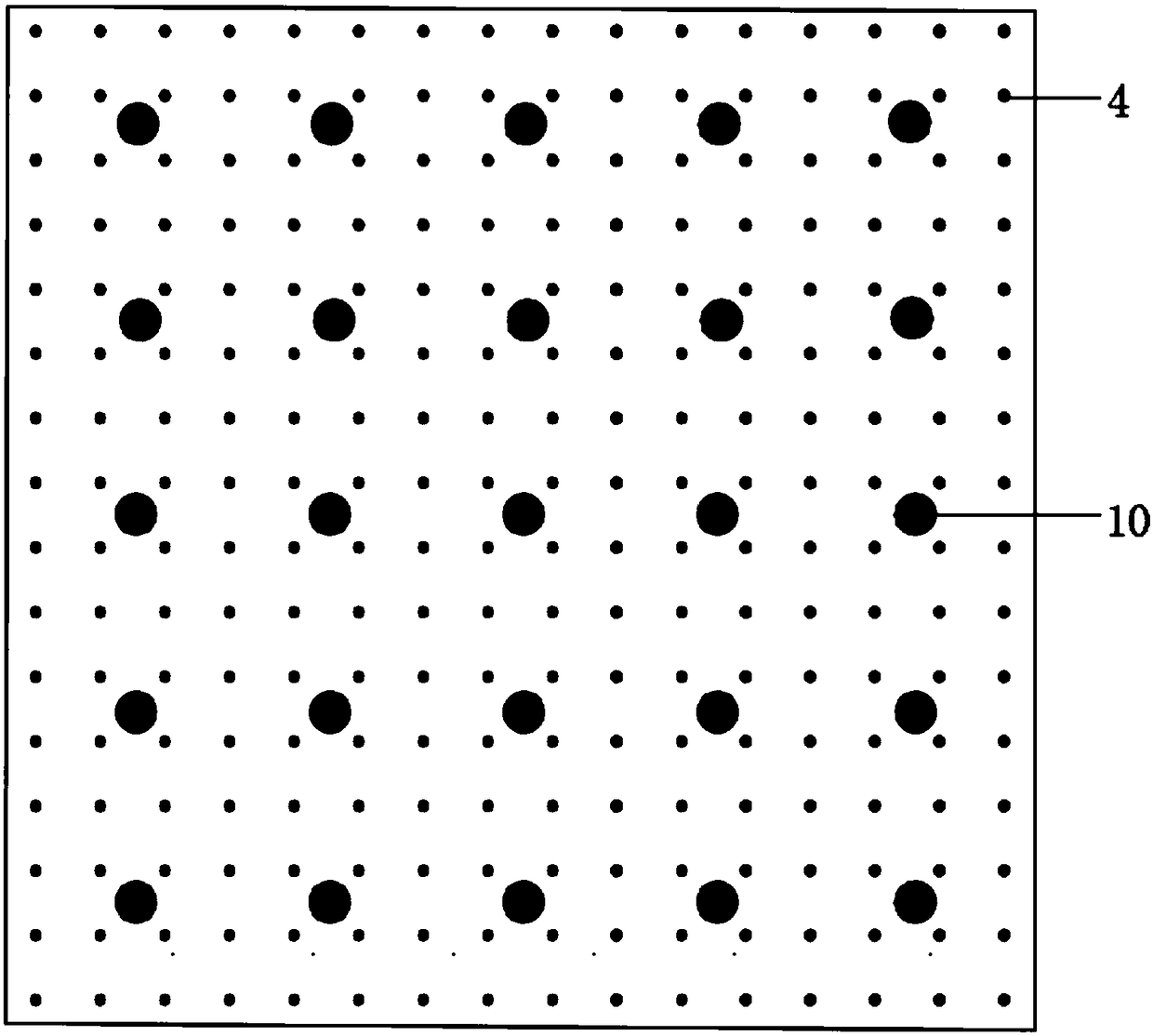
[0078] (1) On the P-type single crystal silicon wafer, 5×5 through holes arranged equidistantly are formed by laser, and the diameter of a single through hole is 300um.
[0079] (2) Anisotropic etching of the P-type monocrystalline silicon wafer after making through holes in a KOH solution at about 80°C to obtain a pyramid structure on the surface.
[0080] (3) Use POCl at 800-900°C 3 The dopant is diffused under low pressure, and an N-type layer is formed on the front surface of the silicon wafer and the surface layer of the through-hole wall. The square resistance after doping is 20Ω / □.
[0081] (4) Spray paraffin wax on the N-type layer according to the array pattern and through holes by inkjet method as a mask. The array pattern is a dot array, the diameter of a single dot is 50um, and the distance between dots is 0.8mm.
[0082] (5) Use wet etching to remove the phosphosilicate glass, back knot and paraffin on the front side of the silicon wafer. A heavy doping is form...
Embodiment 2
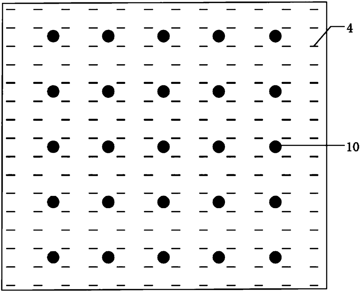
[0090] (1) On the P-type polysilicon wafer, 6×6 through holes arranged equidistantly are formed by laser, and the diameter of a single through hole is 200um.
[0091] (2) Put the P-type polysilicon wafer with through-holes in dry plasma texturing equipment to obtain multi-shaped micro-nano structures, and then perform surface modification in BOE solution.
[0092] (3) by pH 3 As the impurity, it is doped by ion implantation, and then annealed to form an N-type layer on the front surface of the silicon wafer and the surface layer of the through-hole wall. The square resistance after doping is 30Ω / □.
[0093] (4) Spray paraffin wax on the N-type layer according to the array pattern and through holes by inkjet method as a mask. The array pattern is a line segment array, the length of the line segment is 1.5mm, the width is 100um, and the distance between the line segments is 2mm.
[0094] (5) Use wet etching to remove the phosphosilicate glass, back knot and paraffin on the fro...
Embodiment 3
[0102] (1) On the P-type single crystal silicon wafer, 5×5 through holes arranged equidistantly are formed by laser, and the diameter of a single through hole is 400um.
[0103] (2) Put the P-type single crystal silicon wafer after making the through hole in the Cu(NO 3 ) 2 / H 2 o 2 Anisotropic etching was carried out in / HF solution to obtain an inverted pyramid structure on the surface.
[0104] (3) Use POCl at 800-900°C 3 The dopant is diffused under low pressure, and an N-type layer is formed on the front surface of the silicon wafer and the surface layer of the through-hole wall.
[0105] (4) Spray paraffin in the through hole by inkjet method as a mask.
[0106] (5) Use wet etching to remove the phosphosilicate glass, back knot and paraffin on the front side of the silicon wafer.
[0107] (6) Deposit 20nm aluminum oxide and 50nm silicon nitride successively on the back of the silicon wafer by PECVD method; deposit 20nm silicon oxide and 60nm silicon nitride success...
PUM
 Abstract
Description
Claims
Application Information
 - R&D
- Intellectual Property
- Life Sciences
- Materials
- Tech Scout
- Unparalleled Data Quality
- Higher Quality Content
- 60% Fewer Hallucinations
Browse by: Latest US Patents, China's latest patents, Technical Efficacy Thesaurus, Application Domain, Technology Topic, Popular Technical Reports.
© 2025 PatSnap. All rights reserved.Legal|Privacy policy|Modern Slavery Act Transparency Statement|Sitemap|About US| Contact US: help@patsnap.com


