
A pollinator that improves pollen vigor

A technology for pollen vigor and pollinator, which is applied in the field of pollinators, can solve the problems of high labor intensity and high labor intensity, and achieves the effects of simple and reasonable device structure, improving seed setting rate and improving pollen activity.

Active Publication Date: 2020-04-03
钱敬乐
View PDF6 Cites 0 Cited by
  • Summary
  • Abstract
  • Description
  • Claims
  • Application Information

AI Technical Summary

Problems solved by technology

[0002] With the development of agricultural science and technology, the pollination of crops has gradually changed from manual pollination of raw materials to mechanical pollination, but the existing mechanical pollination usually uses pneumatic pollination devices. Although the pollination rate has been improved to a certain extent, the workers in the whole process The labor intensity is still very high. In order to improve this situation, the pollination device is continuously improved, but in the prior art, it is usually an improvement to mechanical equipment, and it is known in the art that when pollination, the live rate of pollen has a great influence on the seed setting rate of fruit, The fruit setting rate has a great influence, and the significance of improving pollination is to improve the fruit setting rate and fruit setting rate, but there is no research on improving the pollen vigor in the existing improvements to the pollination device

Method used


Image

  • A pollinator that improves pollen vigor
  • A pollinator that improves pollen vigor
  • A pollinator that improves pollen vigor

Examples


Embodiment Construction

[0017] The present invention will be further described below in conjunction with the accompanying drawings.

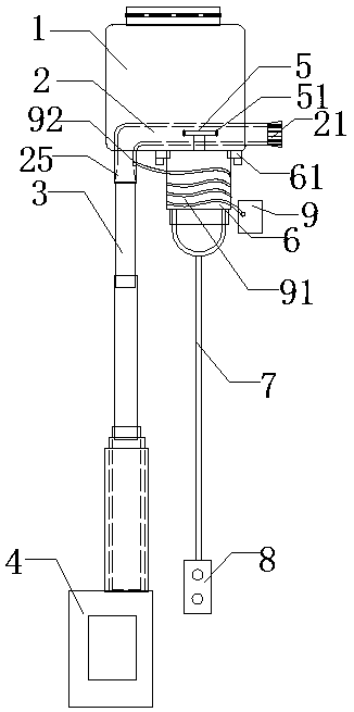
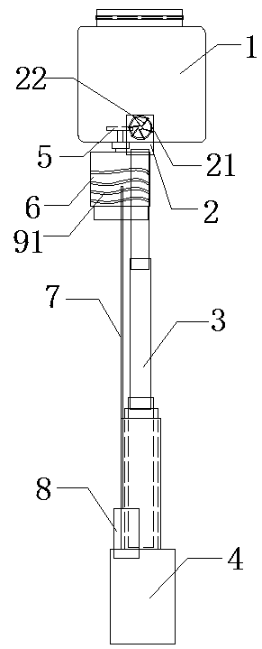
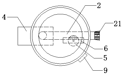
[0018] Such as figure 1 As shown in , a pollinator capable of improving pollen vigor includes a powder storage tank 1, which is provided with an L-shaped tube 2 that runs through the bottom surface and the side of the powder storage tank 1, and the bottom of the L-shaped tube 2 can communicate with each other. Telescopic air flow pipe 3, the electric blower 4 is connected to the bottom of the air flow pipe 3, the pipe diameter of the vertical part of the L-shaped pipe 2 gradually decreases from bottom to top, and the side of the horizontal part of the L-shaped pipe 2 is provided with an air nozzle 21, One side of the wall of the L-shaped tube 2 is provided with a rectangular empty slot (not marked in this figure), and one side of the horizontally rotating wheel piece 5 is arranged in the rectangular empty slot. 2, the part consists of image 3 The middle shaded part ...


PUM


Abstract

The invention belongs to the technical field of mechanical pollination and particularly relates to a pollenator capable of improving the pollen vitality. The pollenator comprises a pollen storage tank, wherein an L-shaped pipe is arranged in the pollen storage tank; the bottom of the L-shaped pipe communicates with a telescopic air flow pipe; the lower part of the telescopic air flow pipe is connected with an electric blower; the pipe diameter of a vertical part of the L-shaped pipe is gradually reduced from bottom to top; an air nozzle is arranged at one side of a transverse part of the L-shaped pipe; a wheel plate part is located in the L-shaped pipe when working; a wheel plate is driven by a motor through a transmission shaft; irregular burrs are distributed on the periphery of the wheel plate; and the motor is controlled by a control device through an electric wire. Compared with the prior art, the pollinator has the advantages that the pollenator is simple and reasonable in structure; a little of pollen is uniformly introduced into the L-shaped pipe through the burrs on the wheel plate and the pollen is mixed with a liquid entrapped in the airflow evenly; the length of the air flow pipe can be adjusted, so that the pollination range and the operability are increased; and the liquid in a liquid storage bag is heated by using heat generated by the motor when working, so that the pollen vitality is improved, thereby improving the setting rate of the pollen.

Description

technical field [0001] The invention belongs to the technical field of mechanical pollination, and in particular relates to a pollinator capable of improving pollen vigor. Background technique [0002] With the development of agricultural science and technology, the pollination of crops has gradually changed from manual pollination of raw materials to mechanical pollination, but the existing mechanical pollination usually uses pneumatic pollination devices. Although the pollination rate has been improved to a certain extent, the workers in the whole process The labor intensity is still very high. In order to improve this situation, the pollination device is continuously improved, but in the prior art, it is usually an improvement to mechanical equipment, and it is known in the art that when pollination, the live rate of pollen has a great influence on the seed setting rate of fruit, The fruit setting rate has a great influence, and the significance of improving pollination i...

Claims


Application Information

Patent Timeline
Patent Type & Authority Patents(China)
IPC IPC(8): A01H1/02
CPCA01H1/027
Inventor 钱敬乐周尽忠
Owner 钱敬乐
Learn More