Punching device with bidirectional punching function

A technology of punching equipment and functions, applied in drilling/drilling equipment, boring/drilling, metal processing equipment and other directions, can solve the problems of large machining error, position offset, low machining accuracy, etc. The effect of stable movement, improved stable positioning, and reduced labor intensity

Inactive Publication Date: 2017-08-04
南京苏宁锻造有限公司
View PDF7 Cites 27 Cited by
  • Summary
  • Abstract
  • Description
  • Claims
  • Application Information

AI Technical Summary

Problems solved by technology

[0002] In the production of enterprises, it is necessary to punch holes in the plate. In some cases, the thickness of the plate is very large. If the hole is drilled on one side, it will be difficult to drill the hole, and the drill bit is easy to break. Offset, it is difficult to ensure the accuracy of the drilling position, and the labor intensity of the workers is high, time-consuming and laborious, resulting in large processing errors and low processing accuracy, which seriously affects the production progress and the quality of the manufactured products, which greatly reduces the drilling machine. Productivity

Method used


Image

  • Punching device with bidirectional punching function
  • Punching device with bidirectional punching function
  • Punching device with bidirectional punching function

Examples


Embodiment Construction

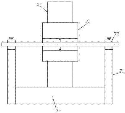
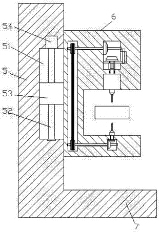
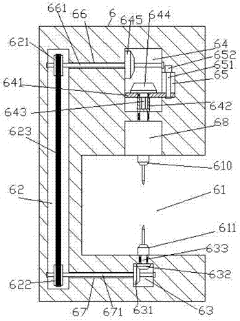
[0021] Such as figure 1 , figure 2 , image 3 with Figure 4 As shown, a kind of punching equipment with two-way punching function of the present invention includes a base 7, a column 5 fixed on the rear end surface of the base 7, and a punching mechanism 6 arranged at the front end of the column 5 , the front end surface of the punching mechanism 6 is provided with a punching execution groove 61, and the inner top wall of the punching execution groove 61 is fixed with a punching motor 68, and the bottom of the punching motor 68 is connected with an upper drill bit. 610, the inner bottom of the punching execution groove 61 opposite to the upper drill bit 610 is provided with a lower drill bit 611, and the inside of the punching mechanism 6 above the punching motor 68 is provided with a switching cavity 64, and the upper drill bit 610 The punching mechanism 6 below is provided with a first transmission cavity 63 inside, and the punching mechanism 6 behind the punching execu...


PUM


Abstract

The invention discloses a punching device with a bidirectional punching function. The punching device comprises a base, a stand column fixed to the end face of the rear side of the base, and a punching mechanism arranged on the front end side of the stand column. A punching executing groove is formed in the end face of the front side of the punching mechanism, and a punching motor is fixedly arranged in the top wall in the punching executing groove. The bottom of the punching motor is cooperatively connected with an upper drill bit, and a lower drill bit is arranged at the position, corresponding to the upper drill bit, in the punching executing groove. A switching cavity is formed in the position, above the punching motor, in the punching mechanism. A first transmission cavity is formed in the position, below the upper drill bit, in the punching mechanism, and a second transmission cavity extending vertically is formed in the position, behind the punching executing groove, in the punching mechanism. A guide groove is formed in the inner wall of the front side of the switching cavity, and a switching driving threaded rod extending in the longitudinal direction is arranged in the guide groove. An inner spline shaft bush with the bottom end rotationally and cooperatively connected with the top end of the punching motor is arranged at the inner bottom of the switching cavity. The punching device is simple in structure, bidirectional punching can be achieved, the punching difficulty is lowered, the punching precision is improved, time and labor are saved, and the rejection rate is reduced.

Description

technical field [0001] The invention relates to the technical field of plate processing, in particular to a punching device with a bidirectional punching function. Background technique [0002] In the production of enterprises, it is necessary to punch holes in the plate. In some cases, the thickness of the plate is very large. If the hole is drilled on one side, it will be difficult to drill the hole, and the drill bit is easy to break. Offset, it is difficult to ensure the accuracy of the drilling position, and the labor intensity of the workers is high, time-consuming and laborious, resulting in large processing errors and low processing accuracy, which seriously affects the production progress and the quality of the manufactured products, which greatly reduces the drilling machine. Productivity. Contents of the invention [0003] The technical problem to be solved by the present invention is to provide a punching device with a bidirectional punching function, which ca...

Claims


Application Information

Patent Timeline
Patent Type & Authority Applications(China)
IPC IPC(8): B23B39/00
CPCB23B39/00
Inventor 陈柯
Owner 南京苏宁锻造有限公司
Why Eureka
Try Eureka