Efficient aeration tank

An aeration tank, high-efficiency technology, applied in the direction of sustainable biological treatment, water/sludge/sewage treatment, biological water/sewage treatment, etc., can solve the problem of single aeration mechanism, difficulty in meeting the needs of sewage treatment, and low aeration efficiency To achieve the effect of improving the aeration effect, increasing the contact area, and fully mixing

Inactive Publication Date: 2017-08-04
HEFEI ZHIHUI LONGTUTENG INTPROP CO LTD
View PDF6 Cites 37 Cited by
  • Summary
  • Abstract
  • Description
  • Claims
  • Application Information

AI Technical Summary

Problems solved by technology

[0002] The aeration tank is a structure that uses the activated sludge method for sewage treatment. A certain sewage residence time is provided in the tank to meet the oxygen required by aerobic microorganisms and the mixing conditions for full contact between the sewage and the activated sludge. The aeration tank is mainly composed of the tank body It consists of three parts, the aeration system and the water inlet and outlet. The pool body is generally made of reinforced concrete, and the plane shape is rectangular, square and circular. The existing aeration methods are mainly divided into blast aeration and mechanical aeration. The existing aeration tanks often have relatively single aeration mechanism and low aeration efficiency, making it difficult to meet people's growing demand for sewage treatment

Method used


Image

  • Efficient aeration tank
  • Efficient aeration tank
  • Efficient aeration tank

Examples


Embodiment Construction

[0017] The following will clearly and completely describe the technical solutions in the embodiments of the present invention with reference to the accompanying drawings in the embodiments of the present invention. Obviously, the described embodiments are only some, not all, embodiments of the present invention. Based on the embodiments of the present invention, all other embodiments obtained by persons of ordinary skill in the art without making creative efforts belong to the protection scope of the present invention.

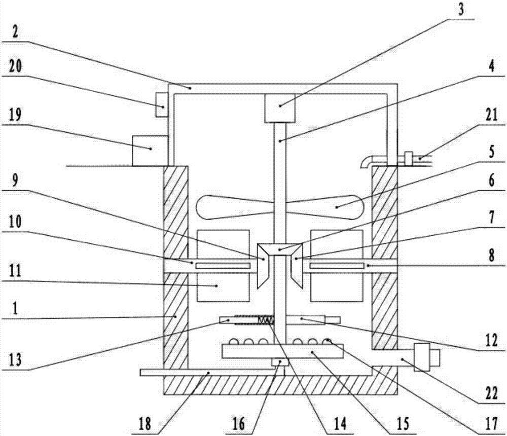
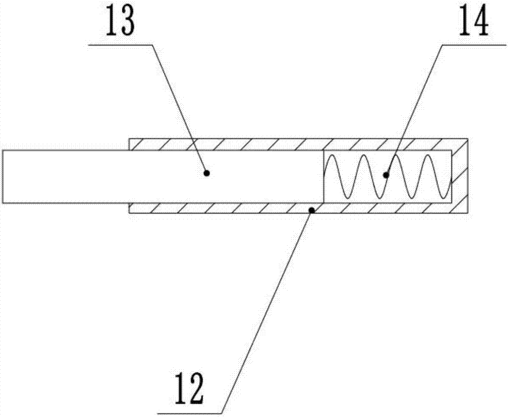
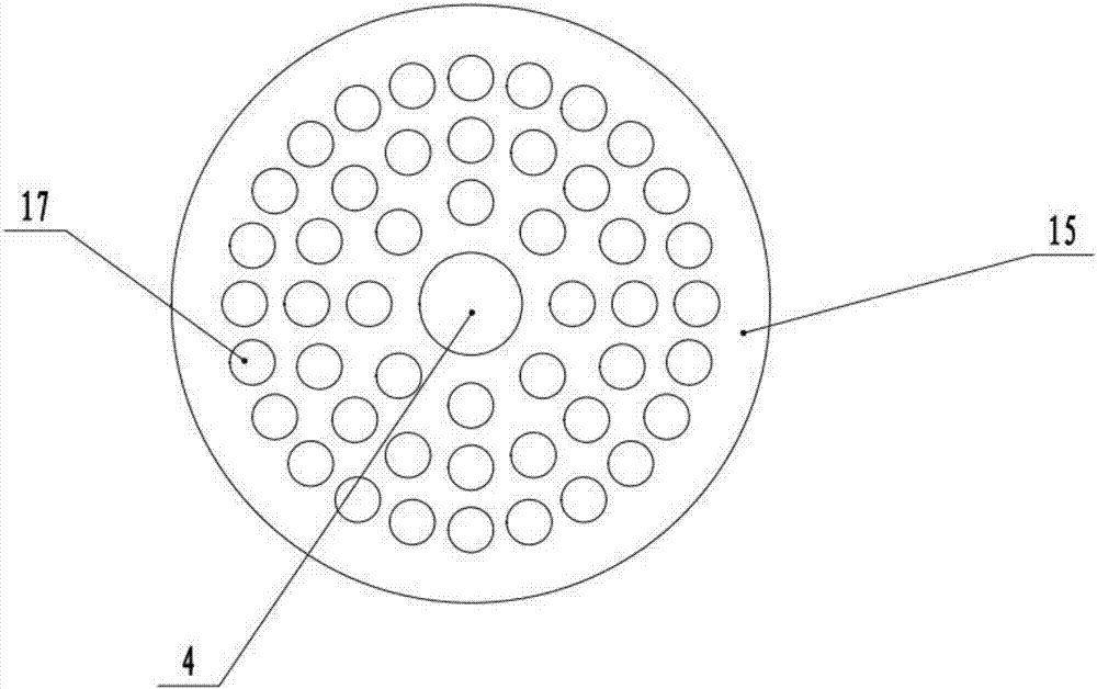
[0018] see figure 1 , 2 , in an embodiment of the present invention, a high-efficiency aeration tank includes a tank wall 1, a bracket 2, a motor 3, a transmission shaft 4, an aeration plate 15, a blower 19, a water inlet pipe 21 and a drain pipe 22, and the pool wall 1 The top of the bracket 2 is fixedly connected to the bracket 2, the lower surface of the bracket 2 is fixedly connected to the motor 3, the shaft extension end of the motor 3 is fixedly connec...


PUM


Abstract

The invention discloses an efficient aeration tank which comprises a tank wall, a bracket, a motor, a transmission shaft, an aeration plate, a blower, a water inlet pipe and a drain pipe, wherein the bracket is fixedly connected with the upside of the tank wall; the lower surface of the bracket is fixedly connected with the motor; a shaft extension end of the motor is fixedly connected with the transmission shaft; a right rotating shaft is rotationally connected with an inner wall on the right side of the tank wall; a left rotating shaft is rotationally connected with an inner wall on the left side of the tank wall; stirring plates are fixed on the left rotating shaft and the right rotating shaft; the tail end of the transmission shaft is fixedly connected with the upper surface of the aeration plate; sewage in a middle layer is turned over vertically by the stirring plates; the sewage and air are mixed more uniformly; the aeration plate exhausts the air into the sewage in a rotating process for aeration of the sewage; the aeration plate exhausts the air while rotating; the air and the sewage are mixed more intensively; the stirring rod scatters bubbles exhausted by the aeration plate; the contact area between the air and the sewage is increased; and an aeration effect is further improved.

Description

technical field [0001] The invention relates to the technical field of sewage treatment equipment, in particular to a high-efficiency aeration tank. Background technique [0002] The aeration tank is a structure that uses the activated sludge method for sewage treatment. A certain sewage residence time is provided in the tank to meet the oxygen required by aerobic microorganisms and the mixing conditions for full contact between the sewage and the activated sludge. The aeration tank is mainly composed of the tank body It consists of three parts, the aeration system and the water inlet and outlet. The pool body is generally made of reinforced concrete, and the plane shape is rectangular, square and circular. The existing aeration methods are mainly divided into blast aeration and mechanical aeration. The existing aeration tanks often have relatively single aeration mechanism and low aeration efficiency, which makes it difficult to meet people's increasing demand for sewage tr...

Claims


Application Information

Patent Timeline
Patent Type & Authority Applications(China)
IPC IPC(8): C02F3/12
CPCC02F3/1284Y02W10/10
Inventor 不公告发明人
Owner HEFEI ZHIHUI LONGTUTENG INTPROP CO LTD
Why Eureka
Try Eureka