Pipe shaft

A pipeline well and pipe body technology, applied in vertical pipelines, pipes, branch pipelines, etc., can solve the problems of pipe material detachment, road subsidence, loose foundation, etc. Reduce the effect of loose foundation

Pending Publication Date: 2017-08-04
BEIJING TOPTP TIANPIN SCI & TECH
View PDF23 Cites 1 Cited by
  • Summary
  • Abstract
  • Description
  • Claims
  • Application Information

AI Technical Summary

Problems solved by technology

[0004] The existing pipe wells and pipes are mostly connected by socket connections. During long-term use, the joints between pipe wells and pipes are easy to loosen. The socket between the well and the pipe is easy to loosen or even disengage. Even a small looseness will cause the problem of water leakage and oil leakage of the pipeline. Water leakage and oil leakage will scour the underground foundation, thus making the foundation near the pipeline well loose. Potholes are even formed, and over time, the pipeline wells will sink, which will separate from the pipes, eventually leading to road surface subsidence

Method used


Image

  • Pipe shaft
  • Pipe shaft
  • Pipe shaft

Examples


Embodiment 1

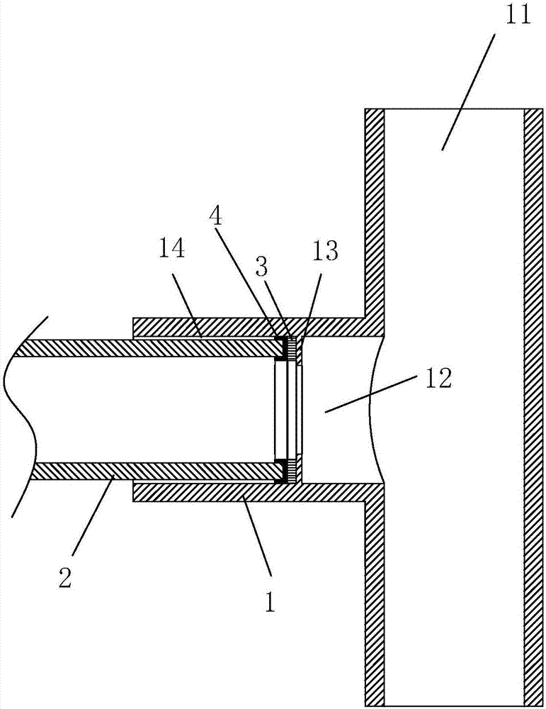
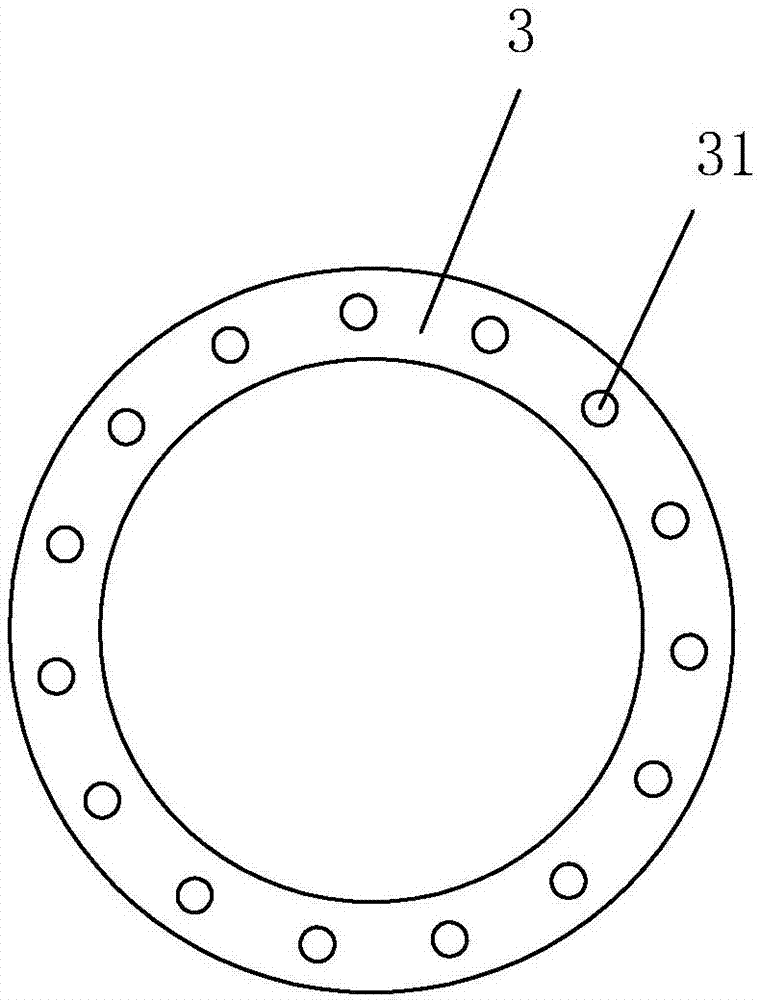
[0044] Embodiment one: a kind of pipeline well, see figure 1 , including a pipe body 1, the pipe body 1 includes an inlet 11 and an outlet 12, when installed, generally the inlet 11 is vertically upward, and the outlet 12 is horizontally oriented. The inner wall of the outlet 12 is provided with an internal thread 14, and the inner wall of the pipe body 1 inside the thread 14 is provided with an annular retaining ring 13, and the retaining ring 13 is integrally formed by protruding inward from the inner wall of the pipe body 1. A rigid ring pad 3 is arranged on the outer side of the retaining ring 13, and the rigid ring pad 3 can be made of hard metals such as iron, copper, stainless steel, or hard plastics such as ABS, POM, PS, PMMA, PC, PET, PBT, and PPO. become. A sealing ring 4 is placed on the outer side of the rigid ring gasket 3, and the cross section of the sealing ring 4 is U-shaped.

[0045] The end of the pipe 2 is provided with an external thread 14 that cooperat...

Embodiment 2

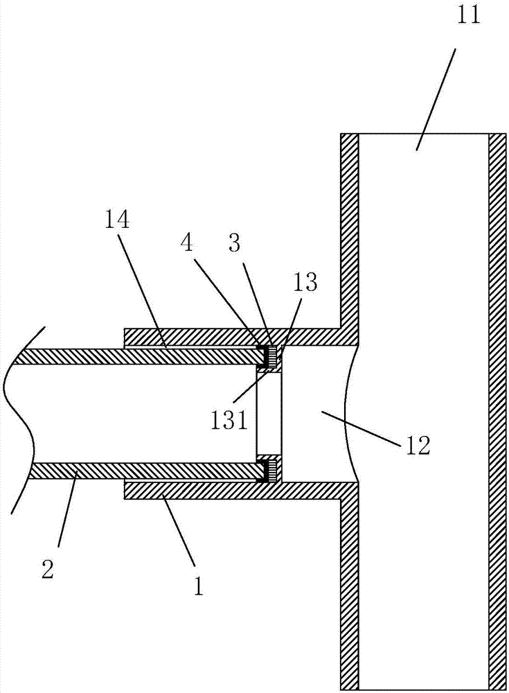
[0047] Embodiment two: a kind of pipeline well, see image 3 The difference between this embodiment and Embodiment 1 is that the inner side of the retaining ring 13 protrudes outward to form a flange 131, and the rigid ring gasket 3 and the sealing ring 4 are placed on the inner wall of the pipe body 1, the retaining ring 13 and the flange 131. within the enclosed space.

Embodiment 3

[0048] Embodiment three: a kind of pipeline well, see Figure 4 The difference between this embodiment and Embodiment 1 is that the internal thread 14 at the outlet 12 is eliminated, the external thread 14 is provided on the outer wall of the outlet 12, and the stop ring 13 is arranged on the outer wall of the pipe body 1 inside the external thread 14.

[0049] At this time, the end of the pipe material 2 is provided with an internal thread 14, and the pipe material 2 is matched with the pipe well to connect the two with the thread 14.


PUM


Abstract

Disclosed is a pipe shaft. According to the technical scheme, the pipe shaft is characterized by comprising a pipe body. The pipe body comprises an inlet and an outlet, wherein threads are formed in the outlet. A blocking portion is arranged on the pipe body, and a sealing ring is arranged on the side, close to the outlet, of the blocking portion. The pipe shaft solves the problem that due to the fact that bell-and-spigot connection is adopted by an existing pipe shaft and a pipe, looseness is caused.

Description

technical field [0001] The invention relates to the pipeline field, more specifically, it relates to a pipeline well. Background technique [0002] Pipeline wells are widely used in municipal engineering, housing construction and other fields, mainly for drainage, sewage discharge, oil discharge or equipment pipeline layout. [0003] Pipe wells made of plastic have been widely used because of their advantages of convenient construction, light weight, and environmental protection. In the existing underground pipeline system, pipeline wells are generally connected with pipes to form a pipeline network, thereby providing channels for urban drainage and sewage. [0004] The existing pipe wells and pipes are mostly connected by socket connections. During long-term use, the joints between pipe wells and pipes are easy to loosen. The socket between the well and the pipe is easy to loosen or even disengage. Even a small looseness will cause the problem of water leakage and oil lea...

Claims


Application Information

Patent Timeline
IPC IPC(8): F16L15/04F16L15/08F16L41/02E04F17/08
CPCF16L15/04F16L15/08F16L41/021E04F17/08
Inventor 吴吕
Owner BEIJING TOPTP TIANPIN SCI & TECH
Why Eureka
Try Eureka