Low-light-loss tube lamp adjusting structure

A technology for adjusting structure and downlight, applied in the field of LED lighting, can solve the problems of limited light control capability, low light output efficiency, light loss, etc.

Inactive Publication Date: 2017-08-04
HUIZHOU CDN INDAL DEV
View PDF3 Cites 45 Cited by
  • Summary
  • Abstract
  • Description
  • Claims
  • Application Information

AI Technical Summary

Problems solved by technology

In the field of downlights, especially for places with high lighting requirements, such as museums, art galleries, high-end clubs, etc., downlights with adjustable irradiation angles are widely used. Most of the existing adjustable downlights on the market are Pin shaft adjustment, this adjustment method is characterized by high light output efficiency when the beam output direction is 0 degrees, but when the

Method used


Image

  • Low-light-loss tube lamp adjusting structure
  • Low-light-loss tube lamp adjusting structure
  • Low-light-loss tube lamp adjusting structure

Examples


Embodiment 1

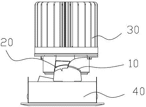
[0025] A low light loss downlight adjustment structure, such as figure 1 As shown, it is connected between the downlight light source part 30 and the light adjustment part 40, and is used as an adjustment mechanism for the output light angle of the downlight light source. The position of the adjustment structure is the same as that of the pin shaft type adjustment structure in the prior art. . It comprises an arc guide part 10 and a sliding part 20 . The arc guide part 10 is used to provide a deflection track for angle adjustment of the light source part. And the sliding part 20 slides on the arc guide part.

[0026] In terms of connection, the arc-shaped guide part 10 is connected to the light-rectifying part 40. The light-rectifying part 40 in the present invention refers to the components at the front end of the downlight, which mostly includes a reflective cup and a fixed frame for fixing the reflective cup. The light output by the part 30 has the function of adjustment...

Embodiment 2

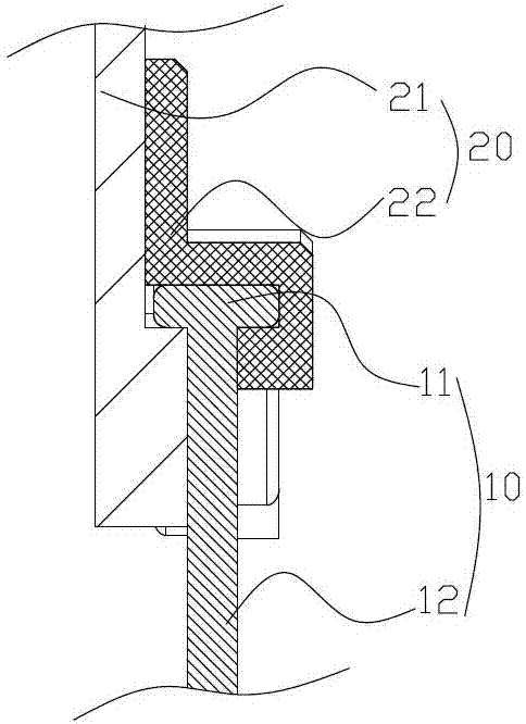
[0029] As a further optimization of embodiment 1, the difference between this embodiment and embodiment 1 is: as figure 2 and image 3 As shown, the arc guide 10 includes a guide bracket 11 and an arc guide rail 12 , wherein the guide bracket 11 is fixed on the lightening unit 40 , and the arc guide rail 12 is connected to the top of the guide bracket 11 . In order to facilitate the connection between the arc-shaped guide part 10 and the sliding part 20, the arc-shaped guide rail 11 in this embodiment is an arc-shaped ridge, and its cross-section is circular or polygonal, and this embodiment is rectangular. The sliding part 20 is sleeved on the arc guide rail 11 , so that the sliding part 20 moves along the arc guide rail 11 .

[0030] In terms of the specific structure of the sliding part 20, the sliding part 20 includes a first clamping part 21 and a second clamping part 22, and the first clamping part 21 and the second clamping part 22 cooperate to wrap the arc-shaped gui...

Embodiment 3

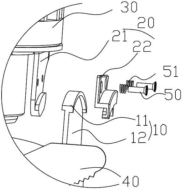
[0035] As a further optimization of embodiment 1, the difference between this embodiment and embodiment 2 is: as Figure 4 As shown, the arc-shaped guide rail 11 in this embodiment is an arc-shaped groove. The arc-shaped groove is also arranged on the top of the guide bracket 11 .

[0036] Regarding the sliding part 20 , the first clamping part 21 and the second clamping part 22 of the sliding part 20 are also arranged on the arc-shaped guide rail 11 , but components passing through the arc-shaped guide rail 11 are required to ensure positioning. In this embodiment, the screw 50 connecting the first clamping portion 21 and the second clamping portion 22 is passed through the arc-shaped guide rail 11 , which plays the role of connection and positioning at the same time.


PUM


Abstract

The invention relates to a low-light-loss tube lamp adjusting structure. The low-light-loss tube lamp adjusting structure is connected between a tube lamp light source part and a light adjusting part, and comprises an arc-shaped guide part arranged on the light adjusting part and a sliding part arranged on the light source part, wherein the sliding part moves along the arc-shaped guide part. The low-light-loss tube lamp adjusting structure has the beneficial effects that the angle adjustment is performed on a light source through the arc-shaped guide structure, and compared with the prior art, under the conditions of the same size of a lamp body, the same beam angle and the same adjusting angle, the light loss is reduced by more than 75% in the adjustment process compared with that of the prior art; the structure of an adjusting device is simple, and parts are easy to manufacture; and due to the fact that the light loss is greatly reduced after adjustment, the low-light-loss tube lamp adjusting structure is of great significance for achieving multiple purposes of one lamp, reducing the models of lamps, reducing the number of molds to be manufactured, and saving social resources.

Description

technical field [0001] The invention relates to the field of LED lighting, in particular to an adjustment structure of a downlight with low light loss. Background technique [0002] With the development of the LED lamp market, more and more lamps with adjustable angles appear. In the field of downlights, especially for places with high lighting requirements, such as museums, art galleries, high-end clubs, etc., downlights with adjustable irradiation angles are widely used. Most of the existing adjustable downlights on the market are Pin shaft adjustment, this adjustment method is characterized by high light output efficiency when the beam output direction is 0 degrees, but when the beam output direction is adjusted to a certain inclination angle, a lot of light is blocked by the lamp body frame and lost , causing the problem of low light extraction efficiency. [0003] Moreover, part of the blocked light will also be reflected by the reflector, causing astigmatism, which m...

Claims


Application Information

Patent Timeline
IPC IPC(8): F21S8/02F21V19/02F21Y115/10
CPCF21S8/02F21V19/02
Inventor 胡永宏邹伟宏赖文威柳保林
Owner HUIZHOU CDN INDAL DEV
Why Eureka
Try Eureka