Rotary type cylindrical drying device

A cylinder drying and rotary technology, applied in drying, drying machines, progressive drying machines, etc., can solve the problems of affecting the quality of textiles, reducing drying efficiency, textiles being damp and hardened, etc., and achieve the effect of water vapor emission Good, avoid impurity clogging, facilitate the effect of water vapor distribution

Inactive Publication Date: 2017-08-04
长兴夹浦正大纺织有限公司
View PDF1 Cites 12 Cited by
  • Summary
  • Abstract
  • Description
  • Claims
  • Application Information

AI Technical Summary

Problems solved by technology

[0003] The cylinder is a cylindrical part, which is divided into driving and driven rollers. It is widely used in various transmission systems such as rotary screen printing machines, digital printers, conveying equipment, papermaking and packaging machinery. It is usually made of seamless steel pipes and is widely used. Used in industries such as steel, metallurgy, coal, cement, power generation, chemical fertilizers, grain depots and ports. The use of rollers in the textile industry is also increasing year by year. As a very important link in textiles, textile printing and dyeing is also increasing the demand for rollers. , but it needs to be dried after printing and dyeing, and the existing drums are mostly used to dry the printed and dyed products by steam heating and drying, the drying efficiency is low, and the quality of the printed and dyed products will be seriously affected if they are not dried in time
[0004] In the Chinese patent with the patent number CN104776695A, a kind of spinning electric heating drying drum is mentioned. The electric heating technology is combined with the drum to make the cloth dry when the drum is driven, which greatly reduces the energy consumption. During the drying process, moisture will be generated, which will make the textiles damp and harden, and the moisture content in the air will increase, reducing the drying efficiency and affecting the quality of the textiles

Method used


Image

  • Rotary type cylindrical drying device
  • Rotary type cylindrical drying device
  • Rotary type cylindrical drying device

Examples


Embodiment

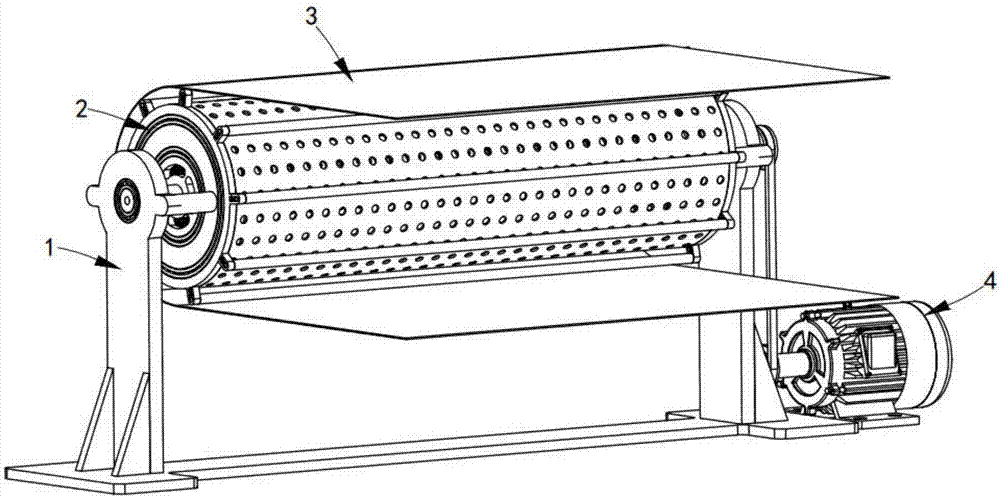
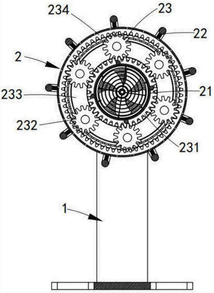
[0052] Such as figure 1 and figure 2 As shown, a rotary drum drying device, including a frame 1, also includes:

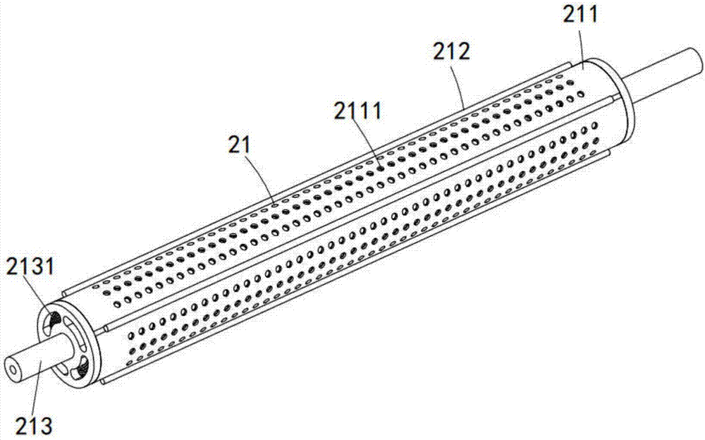
[0053] Drying mechanism 2, the drying mechanism 2 is a cylindrical arrangement, its two ends are rotatably arranged on the frame 1, the cloth 3 is arranged around the drying mechanism 2, and the drying mechanism 2 includes an inner cylinder assembly 21. The outer cylinder assembly 22 and the gear assembly 23 connecting the inner cylinder assembly 21 and the outer cylinder assembly 22;

[0054]A driving mechanism 4, the driving mechanism 4 is arranged on one side of the frame 1, and drives the drying mechanism 2 to rotate through a belt drive.

[0055] It should be noted that the driving mechanism 4 drives the cylindrical drying mechanism 2 to rotate. During the rotation, the inner cylinder assembly 21 rotates clockwise, and the outer cylinder assembly 22 rotates counterclockwise. The inner cylinder assembly 21 generates hot air. The cloth 3 is dried, and the ro...


PUM


Abstract

The invention discloses a rotary cylinder drying device, which divides the cylinder drying mechanism into an inner cylinder component and an outer cylinder component, uses the inner cylinder component to generate hot air, and then relies on the hot air to heat and dry the cloth. During the drying process, the cloth surrounds the outer cylinder assembly, and the outer cylinder assembly and the inner cylinder assembly are synchronously and reversely staggered, and the hot air blown from the inner cylinder assembly changes cyclically, agitating the cloth to form a vibration, so as to facilitate the distribution of moisture and solve the problem In the drying process, the technical problem that the moisture causes the cloth to be damp and hardened, and the quality of the cloth after drying is improved.

Description

[0001] machine technology [0002] The invention relates to the technical field of cloth drying, in particular to a rotary cylinder drying device. Background technique [0003] The cylinder is a cylindrical part, which is divided into driving and driven rollers. It is widely used in various transmission systems such as rotary screen printing machines, digital printers, conveying equipment, papermaking and packaging machinery. It is usually made of seamless steel pipes and is widely used. Used in industries such as steel, metallurgy, coal, cement, power generation, chemical fertilizers, grain depots and ports. The use of rollers in the textile industry is also increasing year by year. As a very important link in textiles, textile printing and dyeing is also increasing the demand for rollers. , but it needs to be dried after printing and dyeing, and the drying of the printed and dyed products by the existing drum is mostly steam heating and drying, the drying efficiency is low, ...

Claims


Application Information

Patent Timeline
Patent Type & Authority Applications(China)
IPC IPC(8): F26B13/18F26B21/00F26B25/20
CPCF26B13/183F26B21/001F26B21/003F26B21/004F26B25/20
Inventor 王会文
Owner 长兴夹浦正大纺织有限公司
Why Eureka
Try Eureka