Measuring device and method for power-transformer-oil-storage-cabinet liquid level

A liquid level measurement device and power transformer technology, which is applied in the direction of measuring devices, liquid/fluid solid measurement, lubrication indicating devices, etc., can solve the problem that the upper and lower limit switching values ​​of the liquid level do not meet the requirements of real-time measurement, collection, and Display function, it is difficult for operation and maintenance personnel to visually observe real-time liquid level data, and it is difficult to meet the requirements of ultra-high or ultra-low liquid level measurement, etc., so as to solve technical problems, avoid mechanical wear and fast processing speed

Inactive Publication Date: 2017-08-04
XIAN UNIV OF SCI & TECH
View PDF5 Cites 3 Cited by
  • Summary
  • Abstract
  • Description
  • Claims
  • Application Information

AI Technical Summary

Problems solved by technology

[0005] When the float linkage mechanism fails, the original pointer measurement display device fails, and the transmission angle of the float linkage mechanism is 0-45 degrees, which is difficult to meet the ultra-high or ultra-low liquid level measurement requirements
Since the oil conservator is installed on the upper side of the main transformer, with a height of more than 5 meters, it is difficult for operation and maintenance personnel to visually observe the real-time liquid level data with the naked eye, and must use instruments such as telescopes
[0006] In the current smart grid construction period, the traditional upper and lower limit switches of liquid level do not meet the functions of real-time measurement, collection and display of liquid level data of oil storage tanks, and cannot realize the signal transmission with the host computer in the main control room

Method used


Image

  • Measuring device and method for power-transformer-oil-storage-cabinet liquid level
  • Measuring device and method for power-transformer-oil-storage-cabinet liquid level
  • Measuring device and method for power-transformer-oil-storage-cabinet liquid level

Examples


Embodiment Construction

[0034] The technical solutions in the embodiments of the present invention will be clearly and completely described below in conjunction with the accompanying drawings in the embodiments of the present invention. The embodiments described herein are only part of the embodiments of the present invention, not all of them. Based on the embodiments of the present invention, all other embodiments obtained by persons of ordinary skill in the art without creative efforts fall within the protection scope of the present invention.

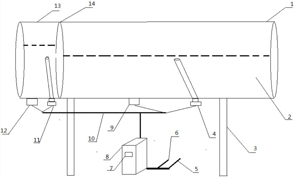
[0035] see figure 1 , the power transformer oil conservator liquid level measuring device and measuring method of the present invention include a transformer oil conservator 1 and a main transformer on-load pressure regulating oil conservator 11, a transformer oil conservator 1 and a main transformer on-load pressure regulating oil conservator 11. Ultrasonic probes are respectively installed at the bottom to calibrate the probes. The ultrasonic probe and t...


PUM


Abstract

The invention discloses a measuring device and method for the power-transformer-oil-storage-cabinet liquid level. The measuring device comprises ultrasonic probes installed at the bottom of a power-transformer oil storage cabinet and calibration probes, the calibration probes are installed inside an oil storage cabinet and communicated with inside insulating oil, the ultrasonic probes and the calibration probes are connected with a data processor through a sensor shield cable, and the data processor is connected with a main engine of a master-control room; the ultrasonic testing method based on the sonar principle is used in liquid level probes, ultrasonic signals directly penetrate through the metal wall of the oil storage cabinet, the wall of the oil cabinet does not need to be punched and installed, mechanical wear caused when a traditional floating-ball-pointer-type mechanical structure runs for a long time is voided, and the technical defects of an original liquid-level measuring device are fundamentally overcome. The measuring method is scientific, accurate and high in measuring accuracy and processor responding speed, and the measuring requirements of the liquid level of a current power-transformer oil storage cabinet of 330 kv or above can be met.

Description

[0001] 【Technical field】 [0002] The invention belongs to the technical field of sonar liquid level electronic measurement, and relates to a liquid level measuring device and a measuring method of a power transformer oil conservator. [0003] 【Background technique】 [0004] At present, most of the 330kV power transformer oil conservator liquid level measurement devices adopt the visual display of the connected glass tube and the measurement method of the pointer float mechanism, which has the following disadvantages: [0005] When the ball float link mechanism breaks down, the original pointer measurement display device fails, and the transmission angle of the ball float link mechanism is 0-45 degrees, which is difficult to meet the ultra-high or ultra-low liquid level measurement requirements. Since the oil conservator is installed on the upper side of the main transformer, with a height of more than 5 meters, it is difficult for operation and maintenance personnel to visuall...

Claims


Application Information

Patent Timeline
Patent Type & Authority Applications(China)
IPC IPC(8): G01F23/296
CPCG01F23/2962
Inventor 岳改丽李柯娜和健陈莎李文党威望郭瑞峰
Owner XIAN UNIV OF SCI & TECH
Why Eureka
Try Eureka