A description method of shaped reflector antenna based on zernike polynomials and trigonometric functions

A technology of trigonometric functions and reflective surfaces, applied in antennas, electrical digital data processing, special data processing applications, etc., can solve problems such as difficulty in deriving from theoretical formulas, complex and difficult expansion forms, and reduced effect of shape-forming process, etc., to achieve convenient processing , the surface is continuous and smooth, and the effect of reducing the optimization variables

Active Publication Date: 2019-09-13
XIDIAN UNIV
View PDF4 Cites 0 Cited by
  • Summary
  • Abstract
  • Description
  • Claims
  • Application Information

AI Technical Summary

Problems solved by technology

In the existing work of describing the shape of the shaped surface, Guan Rui used Bernstein polynomials to expand the generatrix of the shaped reflector in "Research on the Antenna Beamforming of the Hourglass Reflector", but this method can only Shape the axially symmetrical shaped reflecting surface; Li Changze used the non-uniform rational B-spline (NURBS) surface geometric modeling technology to make any reflecting surface The antenna is shaped, and the local shape of the reflector is modified by changing the weighted value of the control point of the reflector, but it is difficult to deduce from the theoretical formula to control the weighted value to describe and analyze the shaped surface; In "Research on Thermal Analysis and Thermal Analysis", the bicubic spline function is used to expand the reference reflective surface. The expansion form is complicated and difficult, which will reduce the effect of the forming process.

Method used


Image

  • A description method of shaped reflector antenna based on zernike polynomials and trigonometric functions
  • A description method of shaped reflector antenna based on zernike polynomials and trigonometric functions
  • A description method of shaped reflector antenna based on zernike polynomials and trigonometric functions

Examples


Embodiment Construction

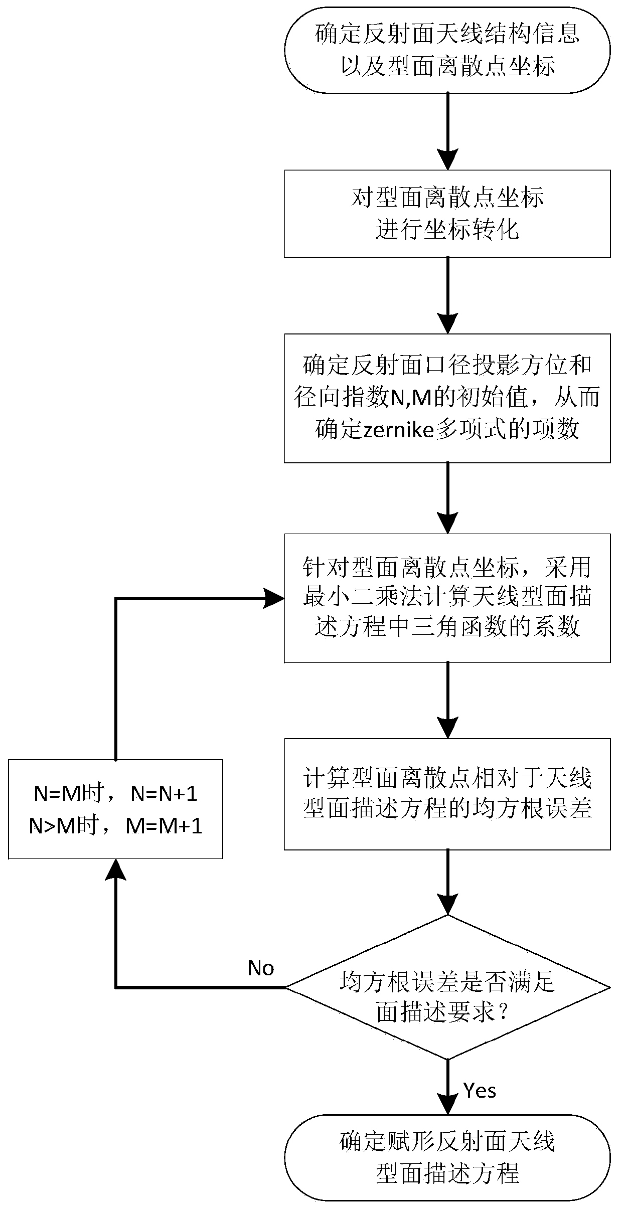
[0031] The invention is described in further detail below in conjunction with the accompanying drawings and embodiments, but is not used as a basis for any limitation of the invention.

[0032] like figure 1 As shown, the shape description method of shaped reflector antenna based on Zernike polynomial and trigonometric functions, the specific steps are as follows:

[0033] Step 1: Determine the panel accuracy allowed by the antenna profile according to the reflector antenna structure information, and obtain the discrete point coordinates of the reflector antenna profile from the electrical designer

[0034] According to the structure information of the antenna reflector panel, the panel accuracy allowed by the shaping surface antenna panel is determined, which is used to verify whether the shaping surface equation meets the profile description requirements at the end. The discrete points of the shaped antenna reflector profile obtained by the electrical designer are used for ...


PUM


Abstract

The invention discloses a shaped reflector antenna surface description method based on a Zernike polynomial and a trigonometric function. The method comprises the steps of determining reflector antenna structure information and a surface discrete point coordinate; conducting coordinate transformation; determining a reflector caliber projection orientation and a radial index initial value in the Zernike polynomial; adopting a least square method to calculate a trigonometric function coefficient in an antenna surface description equation; obtaining the antenna surface description equation composed of the Zernike polynomial and the trigonometric function, and calculating a root-mean-square error relative to a surface discrete point; judging whether the obtained root-mean-square error meets a surface description requirement or not, if yes, obtaining the best shaped reflector antenna surface description equation, and if not, modifying the orientation and a radial index. In the shaped reflector antenna surface description method based on the Zernike polynomial, the antenna surface description mathematical equation can be directly calculated according to the obtained shaped reflector antenna surface discrete point, and essential and precise antenna surface global information is provided for surface switch and performance compensation during observation of an antenna at different frequency bands.

Description

technical field [0001] The invention belongs to the technical field of antennas, in particular to a profile description method of a shaped reflector antenna based on Zernike polynomials and trigonometric functions, which is used for the profile description of a shaped reflector antenna, and is used for profile switching when observing different frequency bands of the antenna. and performance compensation to provide the necessary accurate information on the whole field of the antenna type, which has important academic significance and engineering application value. Background technique [0002] Reflector antennas are mainly used in major projects such as communication radar, astronomical observation, and strategic long-range early warning. In recent years, with the complexity of the working environment of reflector antennas and the diversification of working modes, different functions have put forward different requirements for the antenna. , which also promoted the developme...

Claims


Application Information

Patent Timeline
Patent Type & Authority Patents(China)
IPC IPC(8): G06F17/50H01Q15/14H01Q15/16
CPCG06F30/20H01Q15/14H01Q15/16
Inventor 王从思王浩许谦胡核算杜敬利李鹏张逸群黄进蒋力段宝岩王娜肖岚
Owner XIDIAN UNIV
Why Eureka
Try Eureka