AC power supply management and environment monitoring device for automatic testing system

An automatic test system and AC power supply technology, applied in the direction of circuit devices, electrical components, etc., can solve the problems of small channel power, large tolerance requirements, lack of display screens, etc., and achieve the effect of meeting configuration needs

Inactive Publication Date: 2017-08-04
THE 41ST INST OF CHINA ELECTRONICS TECH GRP
View PDF2 Cites 3 Cited by
  • Summary
  • Abstract
  • Description
  • Claims
  • Application Information

AI Technical Summary

Problems solved by technology

[0007] 1. The main control core uses single-chip microcomputer / ARM, and the work stability is insufficient. Power management is the core of the system work, and the tolerance requirements for power supply and environment must be very large. Using this type of control core often leads to power management downtime and restart.
[0008] 2. Using solid-state relays as the core components of power supply on-off management has very big disadvantages. Its on-off capability for capacitive and inductive loads is weak, and it is difficult to complete on-off stably and effectively. In addition, limited by solid-state relays, there is support The problem of low channel power
[0009] 3. The monitoring and management functions of environment and power parameters are weak, and only data acquisition and alarm can be performed, and no further management and protection actions can be performed
[0010] 4. The cascade management capability of multiple units is weak, that is, the number of slaves that can be accommodated by a single host is small, which is not enough to support the power management needs of the ultra-large-scale automatic test system. The program control address of the slaves cannot be changed freely, and the maintainability is poor
[0011] 5. Lack of display screen support, insufficient human-computer interaction function, the on-off status of each channel, the monitored power supply and environmental parameters, and alarm information cannot be displayed intuitively, which is not conducive to the system operator's first perception to obtain the current status information of the system

Method used


Image

  • AC power supply management and environment monitoring device for automatic testing system

Examples


Embodiment Construction

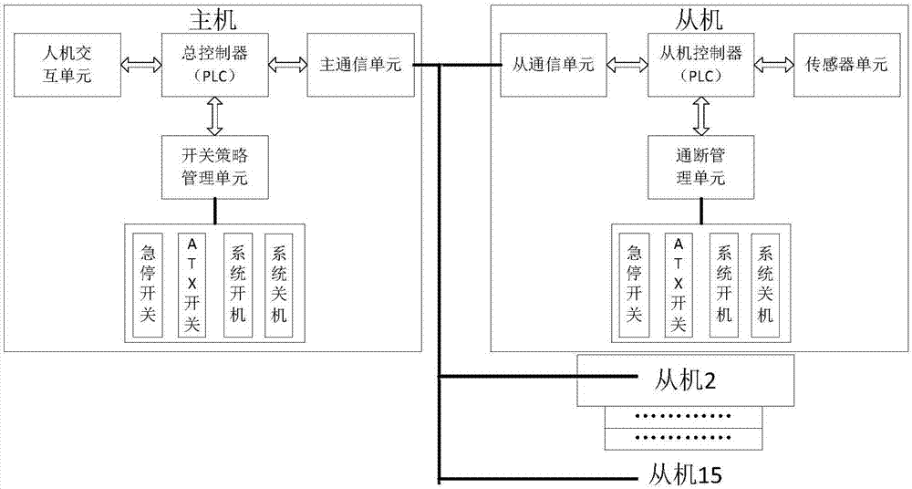
[0032] The specific embodiment of the present invention will be further described below in conjunction with accompanying drawing and specific embodiment:

[0033] Such as figure 1 As shown, an automatic test system AC power supply management and environment monitoring device, including a host, each host is connected to multiple slaves, the host is equipped with a master communication unit, and the slave is equipped with a slave communication unit, the host and the slave The main communication unit and the slave communication unit are used for bus communication. The master also includes a master controller, which is connected to a man-machine interaction unit and a switch strategy management unit. The slave also includes a slave controller, and the slave controller is connected to The sensor unit and the on-off management unit are connected, and the on-off management unit is provided with a contactor. Both the master and the slave use PLC as the control core, which has high st...


PUM


Abstract

The invention discloses an AC power supply management and environment monitoring device for an automatic testing system, and specifically relates to the technical field of AC power supply management testing system monitoring. The device comprises main units, wherein each main unit is connected with a plurality of slave units. Each main unit is provided with a main communication unit, and each slave unit is provided with a slave communication unit. The main communication units and the slave communication units are employed for achieving the bus communication between the main units and the slave units. Each main unit comprises a main controller which is connected with a man-machine interaction unit and a switching strategy management unit. Each slave unit also comprises a slave controller which is connected with a sensor unit and an on / off management unit, wherein the on / off management unit is provided with a contactor. The main units and the slave units employ a PLC as the control core, so the device is high in stability, is high in environment adaptability, and can provide a main control function stably.

Description

technical field [0001] The invention relates to the technical field of test system monitoring, in particular to an automatic test system AC power supply management and environment monitoring device. Background technique [0002] As the scale and integration of automatic test systems increase, an automatic test system often includes multiple cabinets (or assembly boxes), and each cabinet (or assembly box) integrates multiple instruments or PXI / VXI / LXI bus chassis, Due to the large overall power of the system, if all devices in the system are turned on at the same time, there will be various power-on safety problems such as large power-on surge and large leakage current. [0003] With the development of test technology, PXI bus chassis and so on are widely used in test systems, which need to be used in combination with host computers and complex instruments and equipment in various scenarios, such as AC power supply and power-off sequence management, in order to work normally;...

Claims


Application Information

Patent Timeline
Patent Type & Authority Applications(China)
IPC IPC(8): H02J13/00
CPCH02J13/00001H02J13/0062
Inventor 张海庆郭荣斌李智邹德军夏磊宋斌
Owner THE 41ST INST OF CHINA ELECTRONICS TECH GRP
Why Eureka
Try Eureka