Supercharge Your Innovation With Domain-Expert AI Agents!

High-intensity magnetic field die-casting machine

A strong magnetic field, die-casting machine technology, applied in the field of die-casting machines, can solve the problems of air holes, low work efficiency, internal structure disorder, etc., to achieve the effect of enhanced structural strength and toughness, high work efficiency, and fast mold closing speed

Inactive Publication Date: 2017-08-08
JIANGSU HUACHENG ELECTRICAL APP
View PDF1 Cites 3 Cited by
  • Summary
  • Abstract
  • Description
  • Claims
  • Application Information

AI Technical Summary

Problems solved by technology

[0003] At present, horizontal die-casting machines are relatively mature in technology and widely used, but because of the "horizontal" structure, during use, when the molten metal is poured into the melting cup for die-casting, due to There is a lot of air in the melting cup, and the molten metal and air are pressed into the mold at the same time. There will inevitably be pores inside the die-casting metal casting, which seriously affects the quality of the metal casting.
[0004] Although the vertical die-casting machine disclosed in the prior art can better solve the problem of air holes in metal castings, since the mold opening and closing actions are all driven by pure hydraulic devices, and the ejection and other actions are performed separately from the die-casting machine. Completion, slow motion, inefficient work, unable to meet the needs of high-volume production of metal castings
[0005] The internal structure of the metal casting produced by the die-casting machine in the prior art is disordered, resulting in low structural strength and poor toughness of the product

Method used


Image

  • High-intensity magnetic field die-casting machine

Examples


Embodiment Construction

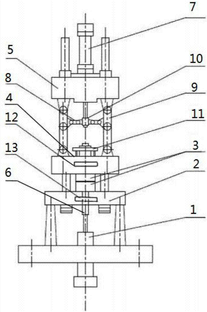
[0016] The present invention will be described in further detail below in conjunction with the accompanying drawings.

[0017] Such as figure 1 As shown, a strong magnetic field die-casting machine includes an injection mechanism, a shaping plate, a mold, a moving plate, and a tail plate arranged sequentially from bottom to top. The shaping plate is provided with a melting cup, and the axis of the tail plate is provided with There is a mold clamping hydraulic cylinder, and several toggle mechanisms are arranged between the tail plate and the movable plate, and the toggle mechanism includes a horizontal support arm, a vertical support arm and a piston rod fixed at the bottom of the mold clamping hydraulic cylinder. The connecting head at the end, the vertical support arm includes an upper support arm and a lower support arm hinged together, the upper support arm is also hinged with the tail plate, the lower support arm is also hinged with the movable plate, and the horizontal s...


PUM


Abstract

The invention discloses a high-intensity magnetic field die-casting machine comprising a pressure injection mechanism, a shaping plate, a mold, a movable template and a tail plate, wherein the pressure injection mechanism, the shaping plate, the mold, the movable template and the tail plate are sequentially arranged from bottom to top. The shaping plate is provided with a molten metal cup. A mold assembly hydraulic cylinder is arranged at the axis of the tail plate. Multiple toggle mechanisms are arranged between the tail plate and the movable template. Each toggle mechanism comprises a transverse bracing arm, a vertical bracing arm and a connector fixed to the bottom end of a piston rod of the mold assembly hydraulic cylinder. Each vertical bracing arm comprises an upper bracing arm body and a lower bracing arm body which are hinged together, wherein the upper bracing arm body is hinged to the tail plate, and the lower bracing arm body is hinged to the movable template. One end of each transverse bracing arm is hinged to the corresponding connector, and the other end of each transverse bracing arm is hinged to the vertical bracing arm. The toggle mechanisms are symmetrically arranged about the axis of the mold assembly hydraulic cylinder. An upper electromagnetic coil is arranged in the movable template. A lower electromagnetic coil matched with the upper electromagnetic coil is arranged in the shaping plate. The upper electromagnetic coil and the lower electromagnetic coil are matched with each other to form a high-intensity magnetic field.

Description

technical field [0001] The invention relates to a die-casting machine, in particular to a high-magnetic field die-casting machine. Background technique [0002] Die-casting machine is an industrial casting machine that hydraulically injects molten metal into a mold for cooling and forming under pressure, and obtains solid metal castings after the mold is opened. Die-casting machines can be divided into horizontal die-casting machines and vertical die-casting machines structurally. [0003] At present, horizontal die-casting machines are relatively mature in technology and widely used, but because of the "horizontal" structure, during use, when the molten metal is poured into the melting cup for die-casting, due to There is a lot of air in the melting cup, and the molten metal and air are pressed into the mold at the same time, and there will inevitably be pores inside the die-casting metal casting, which seriously affects the quality of the metal casting. [0004] Although...

Claims


Application Information

Patent Timeline
IPC IPC(8): B22D17/12B22D17/26B22D17/20
CPCB22D17/12B22D17/20B22D17/2015B22D17/266
Inventor 束荣辉李一俊
Owner JIANGSU HUACHENG ELECTRICAL APP
Features
  • R&D
  • Intellectual Property
  • Life Sciences
  • Materials
  • Tech Scout
  • Unparalleled Data Quality
  • Higher Quality Content
  • 60% Fewer Hallucinations
Learn More