Fan modules and electronics

A technology for a fan module and an electronic device, which is applied to components of a pumping device for elastic fluids, electrical digital data processing, instruments, etc., can solve the problems of air volume loss, affecting the performance of the fan module 100, and reducing elasticity.

Active Publication Date: 2019-02-01
ACER INC
View PDF5 Cites 0 Cited by
  • Summary
  • Abstract
  • Description
  • Claims
  • Application Information

AI Technical Summary

Problems solved by technology

The main disadvantage of the existing dust removal design is that the side wall 112 of the fan housing 110 must have holes, which will easily cause the loss of air volume during normal operation of the fan 120 and affect the performance of the fan module 100
In addition, the design of the dust collection chamber 113 is located outside the side wall 112 of the fan housing 110, resulting in an extra protruding structure of the fan housing 110, which results in less flexibility in the configuration of components in the inner space of the electronic device 150, The position of the fan module 100 is often designed at the corner of the electronic device 150 to prevent the protruding structure from interfering with other mechanical components in the electronic device 150 such as the shaft structure
In addition, since the housing of the electronic device 150 must be additionally perforated 152 to discharge dust (such as image 3 shown), often resulting in considerations and restrictions on the appearance of industrial design

Method used


Image

  • Fan modules and electronics
  • Fan modules and electronics
  • Fan modules and electronics

Examples


Embodiment Construction

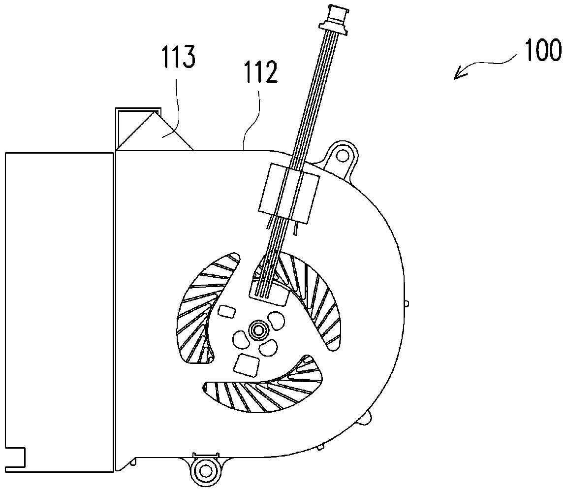
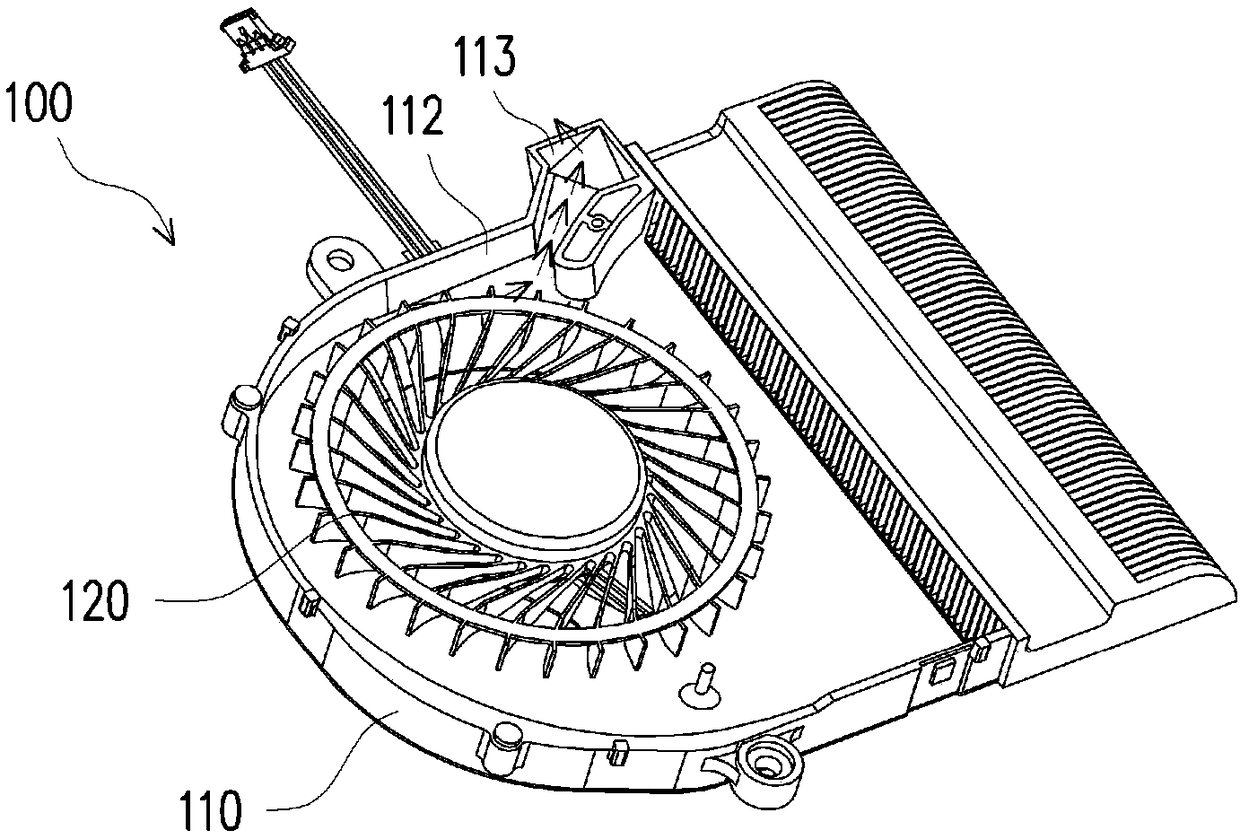
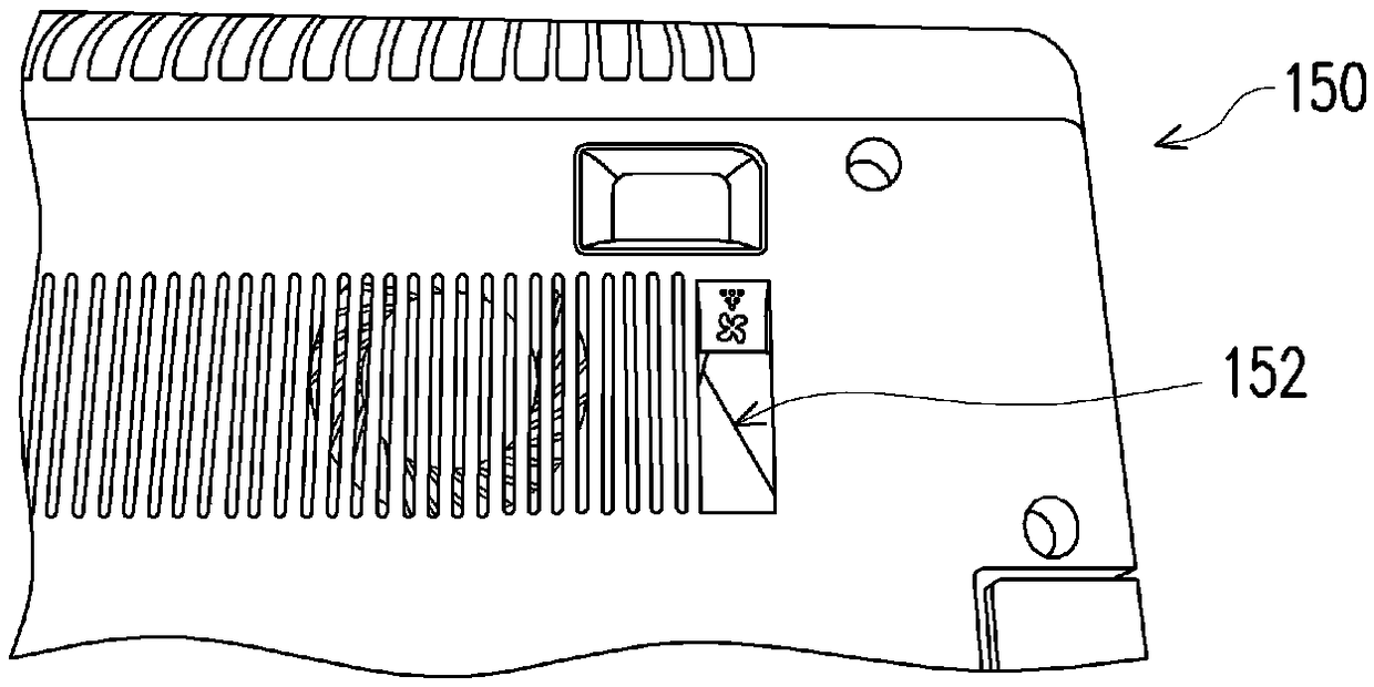
[0046] Figure 4 A schematic diagram of a fan module. Figure 5 for will Figure 4 A schematic diagram of the application of the fan module in an electronic device. Please also refer to Figure 4 and Figure 5 , the electronic device 200 includes a body 210 and a fan module 220 installed in the body 210 . The electronic device 200 is, for example, a notebook computer. The fan module 220 includes a fan housing 222 , a fan 224 and a cooling assembly 226 . The fan casing 222 has an open side 222 a and a closed side 222 b surrounding the open side 222 a, wherein the open side 222 a is provided with a first airflow guiding channel 2221 . The fan 224 is arranged in the fan housing 222, and the cooling assembly 226 is arranged on the open side 222a, and the cooling assembly 226 has a second airflow guiding channel 2261 connected with the first airflow guiding channel 2221, and the air flow caused by the fan 224 The dust is discharged through the first air guiding channel 2221 ...


PUM


Abstract

The invention provides a fan module and an electronic device. The fan module comprises a fan shell, a fan and a heat dissipation assembly; the fan shell is provided with an open side and a closed side surrounding the open side, wherein the open side is provided with a first airflow guide channel; the fan is arranged in the fan shell; the heat dissipation assembly is arranged on the open side and is provided with a second airflow guide channel connected to the first airflow guide channel; and airflow caused by the fan passes through the first airflow guide channel and the second airflow guide channel and is discharged so as to discharge dust. The electronic device comprises a machine body and the fan module, wherein the fan module is arranged in the machine body. According to the fan module and the electronic device, the fan shell of the fan module is not provided with an additional opening in the side wall or a dust collecting cavity, the guide channels allowing air to be discharged are arranged in the fan shell and at the heat dissipation assembly, and therefore the design of the shape and the size of the fan shell can be optimized.

Description

technical field [0001] The invention relates to a fan module and an electronic device, in particular to a structure design different from the known fan module and the electronic device. Background technique [0002] figure 1 and figure 2 is a schematic diagram of an existing fan module, while image 3 It is a partial schematic diagram of the body of the electronic device. Please also refer to figure 1 , figure 2 and image 3 , is currently widely used in the dust removal design of the fan module 100, one of which is to form a dust exhaust channel with holes in the side wall 112 of the fan housing 110, and the dust exhaust channel is connected to the collector outside the side wall 112 of the fan housing 110 The dust chamber 113, through the forward and reverse control circuit, provides cooling wind when the fan 120 is rotating forward, and blows the dust into the dust collecting chamber 113 when the fan 120 is rotating reversely. The main disadvantage of the existin...

Claims


Application Information

Patent Timeline
Patent Type & Authority Patents(China)
IPC IPC(8): F04D29/54F04D29/58F04D29/70G06F1/20
CPCF04D29/545F04D29/582F04D29/703G06F1/203
Inventor 林光华廖文能谢铮玟
Owner ACER INC
Why Eureka
Try Eureka