Check patentability & draft patents in minutes with Patsnap Eureka AI!

Light emitting device

A technology for light-emitting devices and light-emitting chips, which is applied to semiconductor devices, electric solid-state devices, and semiconductor devices of light-emitting elements, can solve the problems of light output fading and reliability reduction of light-emitting devices, and improve light output efficiency and heat dissipation efficiency. , the effect of improving reliability and life

Inactive Publication Date: 2017-08-08
LG INNOTEK CO LTD
View PDF18 Cites 0 Cited by
  • Summary
  • Abstract
  • Description
  • Claims
  • Application Information

AI Technical Summary

Problems solved by technology

As a result, the light output of the light emitting device is degraded and the reliability is reduced

Method used


Image

  • Light emitting device
  • Light emitting device
  • Light emitting device

Examples


no. 1 example

[0021] Configuration example of the first embodiment

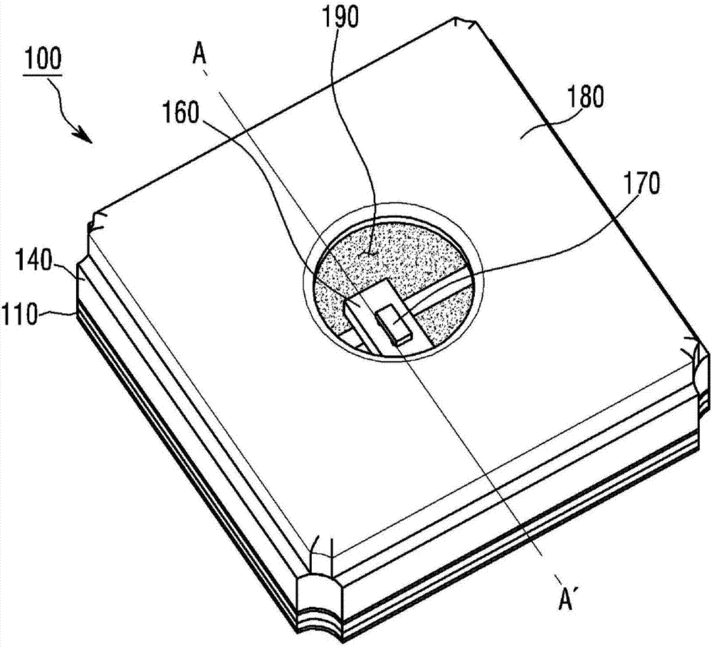
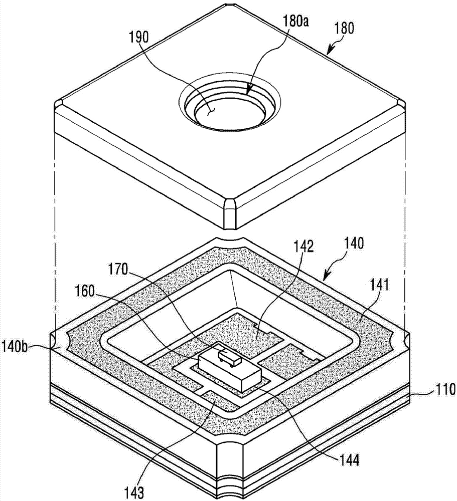
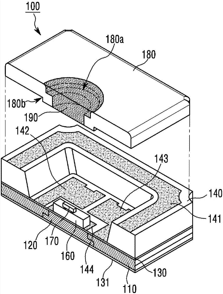
[0022] Figure 1 to Figure 7 is a view of the light emitting device according to the first embodiment. figure 1 is a perspective view of the light emitting device according to the first embodiment. figure 2 for figure 1 An exploded perspective view of the light-emitting device shown. image 3 for cutting along the line A-A' by figure 1 An exploded view of the light-emitting device formation shown. Figure 4 for cutting along the line A-A' by figure 1 A cross-sectional view of the light-emitting device formation shown. Figure 5 to Figure 7 is a cross-sectional view showing the design dimensions of the light emitting device.

[0023] Such as Figure 1 to Figure 4 As shown, the light emitting device 100 according to the first embodiment includes: a substrate 110; a main body 140, which is arranged on the substrate 110 and has a through hole 140a formed therein; at least one light emitting chip 170, which is arranged...


PUM


Abstract

A light emitting device may be provided that includes: a substrate; a body which is disposed on the substrate and has a first hole having a predetermined size; a light emitting chip which is disposed within a cavity formed by the substrate and the first hole of the body; a cap which is disposed on the body and has a second hole having a predetermined size; and a transparent window which is disposed in the second hole, wherein a lower portion of the cap is divided into a first surface and a second surface more projecting downwardly than the first surface and wherein at least a portion of the first surface is attached and fixed to the body.

Description

[0001] This application is a divisional application of an invention patent application with the application number 201310346581.X, the application date is August 9, 2013, and the invention name is "light emitting device". technical field [0002] This embodiment relates to a light emitting device. Background technique [0003] With the development of both thin film growth technology and constituent materials, light-emitting devices (including laser diodes or light-emitting diodes) formed by using Group III to Group V or Group II to Group VI compound semiconductor materials of semiconductors can produce various Different colors of light (such as red light, green light, blue light) and ultraviolet light. Light emitting devices are also capable of producing highly efficient white light by using fluorescent materials or by mixing these colors. Compared with existing light sources such as fluorescent lamps and incandescent lamps, the light emitting device has advantages of low p...

Claims


Application Information

Patent Timeline
Patent Type & Authority Applications(China)
IPC IPC(8): F21K9/20F21V19/00F21V29/503F21V29/70F21V29/83F21Y115/10
CPCF21V29/503F21V29/70F21V29/83F21V19/001H01L33/486H01L33/58H01L2924/0002H01L2924/00H01L33/48H01L33/642
Inventor 金炳穆小平洋郑粹正姜宝姬鲁永珍反田祐一郎大关聪司
Owner LG INNOTEK CO LTD
Features
  • R&D
  • Intellectual Property
  • Life Sciences
  • Materials
  • Tech Scout
  • Unparalleled Data Quality
  • Higher Quality Content
  • 60% Fewer Hallucinations
Learn More