
Gaseous fuel mixing device

A technology of mixing device and gaseous fuel, which is applied to gas fuel burners, burners, combustion methods, etc., can solve the problems of easy blockage of gasification devices, complex structure of liquid combustion devices, and poor gasification effect, etc. Effect

Pending Publication Date:
View PDF13 Cites 3 Cited by
  • Summary
  • Abstract
  • Description
  • Claims
  • Application Information

AI Technical Summary

Problems solved by technology

Current alcohol-based fuel gasification combustion devices have problems such as poor gasification effect and easy blockage of gasification devices, while liquid combustion devices are often relatively complex in structure and not stable in effect
In addition, the way of ignition and gasification in the burner is often difficult to effectively control the air excess coefficient to ensure low-nitrogen combustion

Method used


Image

  • Gaseous fuel mixing device
  • Gaseous fuel mixing device

Examples


Embodiment Construction

[0016] The specific structure, operation method and implementation method of the present invention will be discussed in detail below in conjunction with the accompanying drawings and embodiments.

[0017] The orientation terms such as up, down, left, right, front and rear in this application document are established based on the positional relationship shown in the drawings. If the drawings are different, the corresponding positional relationship may also change accordingly, so this should not be understood as limiting the scope of protection.

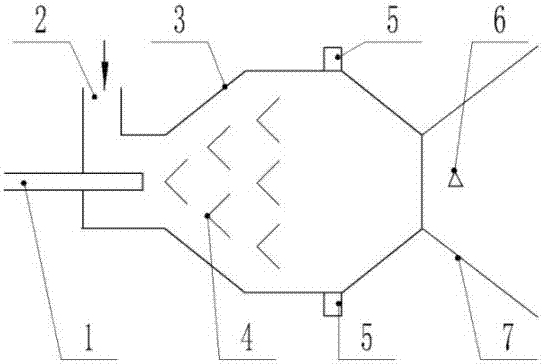
[0018] A gaseous fuel mixing device according to the present invention comprises a fuel injection pipe 1, a primary air pipe 2 and a mixing chamber 3, such as figure 1 shown. In the description of the embodiments, the inlet of the fuel in the mixing chamber is referred to as the front, and the outlet is referred to as the rear. The fuel injection pipe 1 and the primary air pipe 2 are arranged at the front end of the mixing chamber 3,...


PUM


Abstract

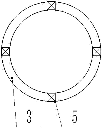
The invention provides a gaseous fuel mixing device. The gaseous fuel mixing device comprises a fuel injection pipe, a primary air pipe and a mixing chamber. The fuel injection pipe and the primary air pipe are arranged at the front end of the mixing chamber. The mixing chamber expands and contracts gradually with the two ends being narrow and the middle portion being wide. Umbrella-shaped diffusion cones which are arrayed in a stepped mode are arranged in the mixing chamber, and the number of the next-stage umbrella-shaped diffusion cones is larger than the number of the prior-stage umbrella-shaped diffusion cones. Secondary air pipes are further arranged behind the mixing chamber, secondary air sprayed in from the secondary air pipes enters the mixing chamber in the tangential direction, and the rotational flow direction of the secondary air is opposite to rotational flow direction of the primary air. The gaseous fuel mixing device has the advantages that the disturbance capacity is high, and fuel and air are evenly mixed.

Description

technical field [0001] The invention relates to a gaseous fuel mixing device, in particular to a mixing device in a low-nitrogen burner after the vaporized low-boiling fuel or the gaseous fuel itself. Background technique [0002] As the public pays more attention to atmospheric pollution, the pollution of coal-fired industrial boilers and small boilers is facing more severe pressure to control or shut down. Therefore, clean coal utilization technology has received more and more attention. At the same time, looking for clean alternative energy is also a solution, such as renewable energy such as biomass, or natural gas, alcohol-based fuels, etc. [0003] Alcohol-based fuels are generally low-boiling fuels, which are relatively easy to completely decompose and burn, and are a relatively clean alternative energy source. However, the relatively mature ignition and combustion devices are oil or gas burners, which are not completely suitable for alcohol-based fuels. Various com...

Claims


Application Information

Patent Timeline
Patent Type & Authority Applications(China)
IPC IPC(8): F23D14/02F23D14/62F23D14/46
CPCF23D14/02F23D14/46F23D14/62
Inventor 张国义张凝
Learn More