Eureka AIR delivers breakthrough ideas for toughest innovation challenges, trusted by R&D personnel around the world.

Deep dehumidification air handling unit

A wet air and unit technology, which is applied in the direction of using air flow as shielding, air conditioning system, space heating and ventilation, etc., can solve the problems that the air conditioning unit cannot accurately adjust the indoor humidity, and the single control effect is not ideal, so as to enhance the dehumidification effect. , Improve work performance and safety performance, the effect of large humidity adjustment margin

Inactive Publication Date: 2017-08-08
NANJING NORMAL UNIVERSITY
View PDF7 Cites 5 Cited by
  • Summary
  • Abstract
  • Description
  • Claims
  • Application Information

AI Technical Summary

Problems solved by technology

Ordinary air handling units can only handle the air in one kind of air supply state. When the operating conditions of each tested unit change greatly, especially for some tested units that require a large amount of dehumidification, ordinary air handling units cannot meet its requirements
[0003] Patent CN102620490A discloses an air conditioner unit with fresh air dehumidification and dry coil refrigeration. The air conditioner unit controls air temperature and humidity separately, and uses high temperature water in the dry coil to control the indoor temperature to prevent condensed water in the dry coil. The generated low-temperature water is dehumidified by the fresh air unit. Although the temperature and humidity are independently controlled, the overall effect is acceptable when the requirements are not high, but the individual control effect of the air conditioning unit on humidity is not ideal. Indoor ambient humidity requires precise adjustment of indoor humidity

Method used


Image

  • Deep dehumidification air handling unit
  • Deep dehumidification air handling unit
  • Deep dehumidification air handling unit

Examples


Embodiment Construction

[0032] Below in conjunction with embodiment technical solution of the present invention is made more specific description:

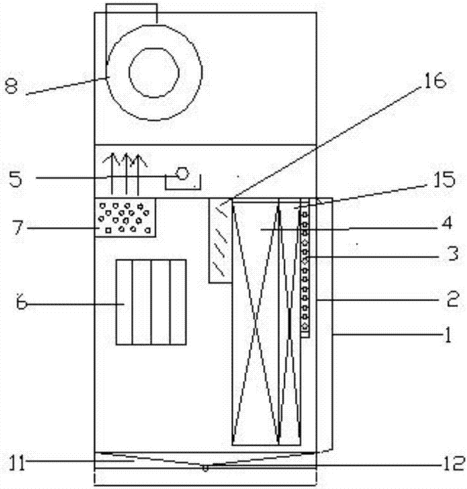
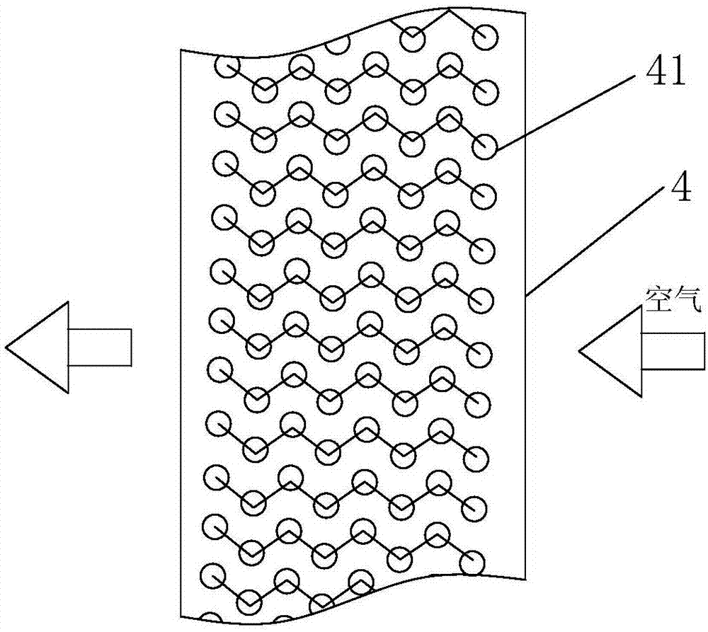
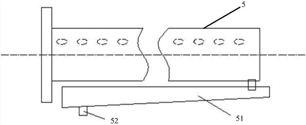
[0033] The present invention includes a unit box 2, which is provided with a return air outlet 1 with a primary filter, and the unit box 2 is provided with an evaporator 4, a rear electric heater 7, and a dry steam humidifier. Nozzle 5 and fan 8; the air entering the unit box 2 from the air return port 1 flows through the evaporator 4 to be cooled and dehumidified, and then enters the rear electric heater 7 to be heated to the required temperature, and then Humidify to the required humidity by the dry steam humidifying nozzle, and finally send it to the test room of the enthalpy difference laboratory through the fan 8; Adjustable outlet damper 16. The outlet air valve 16 includes a shutter, which covers the area of ​​the air outlet of the evaporator 4. When the air needs to be deeply dehumidified, the area of ​​the return air outlet can be blocked by ad...


PUM


Abstract

The invention relates to a deep dehumidification air handling unit. The deep dehumidification air handling unit comprises an unit box body; the unit box body is provided with an air return port with a primary filter screen; an evaporator, a rear electric heater, a dry steam humidification spraying pipe and a fan are arranged in the unit box body; air fed in the unit box body from the air return port flows through the evaporator for cooling and dehumidification, enters the rear electric heater for heating to reach the needed temperature, is humidified to reach the needed humidity by the dry steam humidification spraying pipe, and is finally fed in a testing room through the fan; and an exhaust port of the evaporator is provided with an outlet air valve for adjusting the flow of the air flowing through the evaporator. The deep dehumidification air handling unit realizes adjustment of the flow of the air flowing through the evaporator through adjusting the openness of the outlet air valve. When the refrigeration capacity of the evaporator is invariable, the enthalpy difference of the air passing through an access port of the evaporator is increased to achieve the effect of improving low-air-volume and high-enthalpy-difference dehumidification; and the deep dehumidification air handling unit can meet the temperature and humidity requirements of tested units more precisely.

Description

technical field [0001] The invention belongs to the technical field of air-conditioning enthalpy difference test equipment, and in particular relates to a deep dehumidification air processing unit. Background technique [0002] The air-conditioning and refrigeration equipment performance test device of the enthalpy difference method often requires an air handling unit to control the temperature and humidity of the test environment to meet the operating conditions of the tested unit. For example, when the air-cooled cold air unit type air conditioner is subjected to the nominal cooling performance test, the dry and wet bulb temperature between the outdoor test environment should be controlled at 35°C / 24°C, while the dry and wet bulb temperature between the indoor test environment should be controlled at 27°C / 19°C, the dry and wet bulb temperature control between the outdoor and indoor test environments is realized through the air handling unit. Ordinary air handling units ca...

Claims


Application Information

Patent Timeline
Patent Type & Authority Applications(China)
IPC IPC(8): F24F1/02F24F3/14F24F3/153F24F11/04F24F12/00
CPCF24F3/14F24F3/153F24F11/74F24F12/001F24F2003/1452
Inventor 张忠斌姚喻晨王晓琴陈智明
Owner NANJING NORMAL UNIVERSITY
Why Eureka
Eureka Blog
Learn More