Eureka AIR delivers breakthrough ideas for toughest innovation challenges, trusted by R&D personnel around the world.

Thermal error compensation system and method for embedded full-life-cycle machine tool

A full life cycle, compensation system technology, applied in the field of embedded full life cycle machine tool thermal error compensation system, can solve the problems of impact effect, unverified machine tool thermal error consistency, unfavorable user convenience, etc., to achieve thermal error Effect

Active Publication Date: 2017-08-08
无锡超通智能制造技术研究院有限公司
View PDF6 Cites 6 Cited by
  • Summary
  • Abstract
  • Description
  • Claims
  • Application Information

AI Technical Summary

Problems solved by technology

This system has strong adaptability and can be used for experimental modeling of various machine tools, but there are two problems. The first is that each experiment needs to use a laser interferometer to measure the error. For a single machine tool, the laser interferometer can be used Accurate measurement and modeling, but the consistency of machine tool thermal error has not been verified. A large number of machine tools need to be tested one by one. For machine tools that have already been sold, it is very difficult to conduct experiments again, which is not conducive to the convenience of users.
The second is that it takes a long time to occupy the network port for communication. When the actual machine tool is used for processing, the network port needs to perform other operations, which will cause great inconvenience to the machine tool user to arrange work.
In terms of model establishment, although the above-mentioned measurement device can establish a thermal error model more accurately, the thermal error model of the machine tool will change with the use of the machine tool, and the model needs to be corrected in time. The operation of the above-mentioned modeling experiment is complicated and repeated The cost of experimentation is high, which affects the effect of actual use

Method used

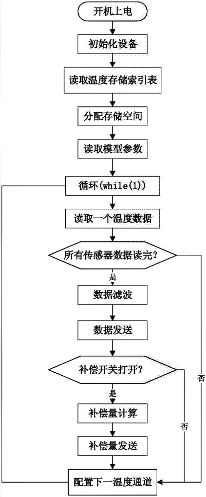

Image

  • Thermal error compensation system and method for embedded full-life-cycle machine tool
  • Thermal error compensation system and method for embedded full-life-cycle machine tool
  • Thermal error compensation system and method for embedded full-life-cycle machine tool

Examples


Embodiment Construction

[0022] The present invention is described in further detail below in conjunction with accompanying drawing:

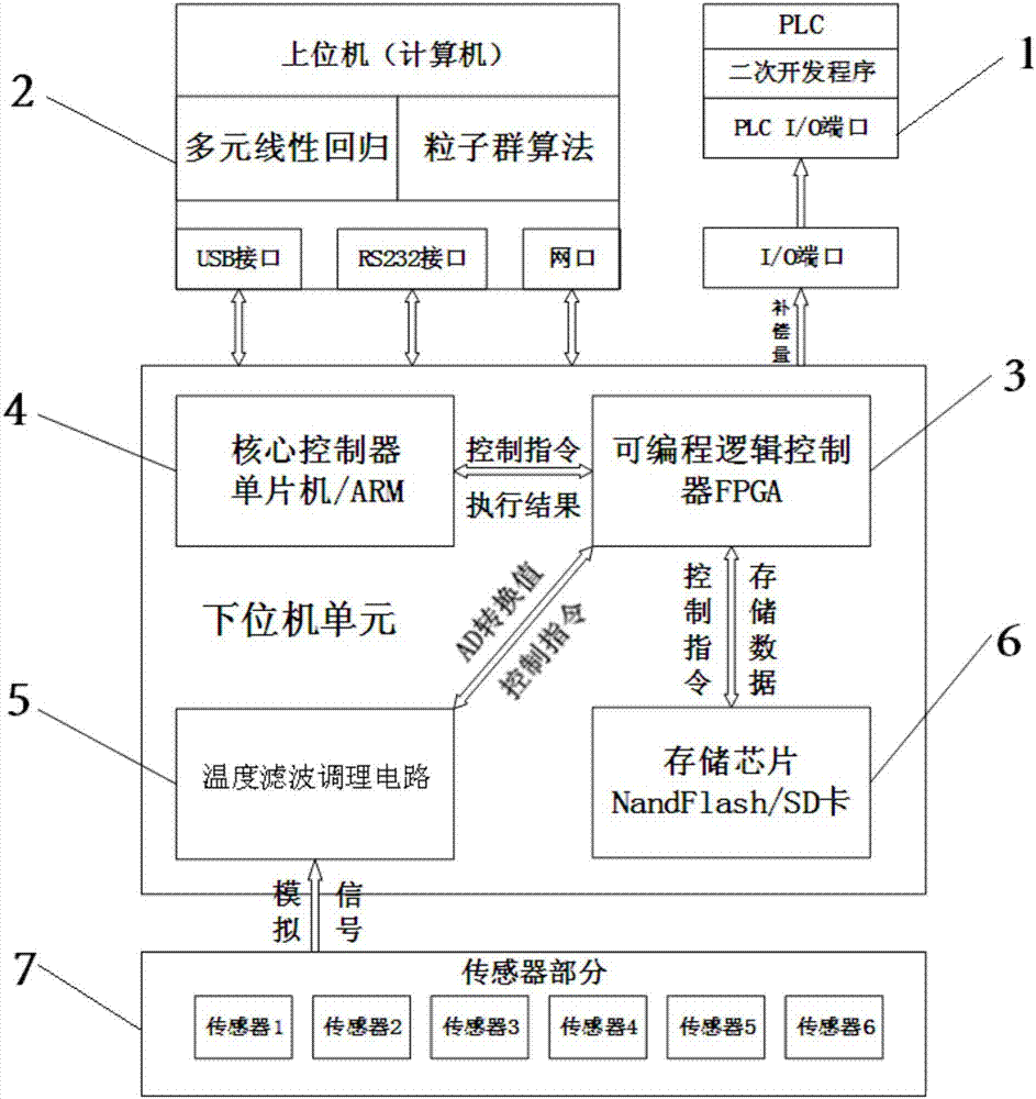
[0023] refer to figure 1 , the embedded full life cycle machine tool thermal error compensation system of the present invention includes a host computer 2, a PLC controller 1, a core controller 4, a programmable logic controller 3, a temperature filter conditioning circuit 5, a memory chip 6 and a A temperature sensor 7 for collecting the temperature of the machine tool, wherein the output end of the temperature sensor 7 is connected to the programmable logic controller 3 through the temperature filter conditioning circuit 5, and the programmable logic controller 3 is connected to the memory chip 6, the PLC controller 1 and the core control The device 4 is connected, and the upper computer 2 is connected with the core controller 4.

[0024] The programmable logic controller 3 is connected to the PLC controller 1 through the I / O port; the core controller 4 is connected...


PUM


Abstract

The present invention discloses a thermal error compensation system and a method for an embedded full-life-cycle machine tool. The system comprises a host computer, a PLC (programmable logic controller), a core controller, a programmable logic controller, a temperature filtering and conditioning circuit, a storage chip and a temperature sensor used for collecting the temperature of a machine tool. The output end of the temperature sensor is connected with the programmable logic controller through the temperature filtering and conditioning circuit. The programmable logic controller is connected with the storage chip, the PLC and the core controller. The host computer is connected with the core controller. Based on the system and the method, the thermal error compensation of the machine tool is realized precisely, and the operation is relatively simple.

Description

technical field [0001] The invention belongs to the field of thermal error compensation of numerical control machine tools, and relates to an embedded full life cycle machine tool thermal error compensation system and method. Background technique [0002] With the improvement of parts processing accuracy and machine tool assembly technology, the errors caused by manufacturing and assembly of traditional machine tools have dropped significantly, while thermal errors, which were not the main factor before, accounted for 40% to 70% of modern processing errors. Error compensation technology is getting more and more attention. Among the two methods of thermal balance design and thermal error reverse compensation, the second one is widely used because of its short development cycle and good versatility. Thermal error reverse compensation requires a high-efficiency, high-precision, and high-reliability compensation device. For example, the patent with the application number 201511...

Claims


Application Information

Patent Timeline
Patent Type & Authority Applications(China)
IPC IPC(8): G05B19/404
CPCG05B19/404G05B2219/37509
Inventor 陶涛颜宗卓梅雪松侯瑞生杜宏洋姜歌东
Owner 无锡超通智能制造技术研究院有限公司
Why Eureka
Eureka Blog
Learn More