Power generation apparatus

A power generation device and coil technology, which is applied in the electronic field, can solve the problems of bulky power generation device, low conversion efficiency, and low power generation, and achieve the effects of mature and stable manufacturing process, high conversion efficiency, and high power generation

Active Publication Date: 2017-08-08
杜曦阳
View PDF15 Cites 0 Cited by
  • Summary
  • Abstract
  • Description
  • Claims
  • Application Information

AI Technical Summary

Problems solved by technology

Some existing power generation devices use wind power, water power and other kinetic energy to drive the rotor to rotate continuously to cut the magnetic field lines, thereby generating electric energy to achieve the purpose of power generation, but this kind of power generation device is relatively heavy and bulky, and is not easy to carry
Some use the kinetic energy generated by the biological movement to drive the magnetic parts to reciprocate and cut the magnetic field lines, but the biological is not moving all the time, and the conversion efficiency is low, so the power generation of this power generation device is extremely low, and the electric energy generated is very little , not very practical

Method used


Image

  • Power generation apparatus
  • Power generation apparatus
  • Power generation apparatus

Examples


Embodiment Construction

[0029] It should be understood that the specific embodiments described here are only used to explain the present invention, not to limit the present invention. The following will clearly and completely describe the technical solutions in the embodiments of the present invention with reference to the accompanying drawings in the embodiments of the present invention. Obviously, the described embodiments are only part of the embodiments of the present invention, not all of them. Based on the embodiments of the present invention, all other embodiments obtained by persons of ordinary skill in the art without creative efforts fall within the protection scope of the present invention.

[0030] It should be noted that all directional indications (such as up, down, left, right, front, back...) in the embodiments of the present invention are only used to explain the relationship between the components in a certain posture (as shown in the accompanying drawings). Relative positional rela...


PUM


Abstract

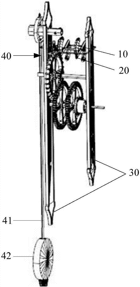
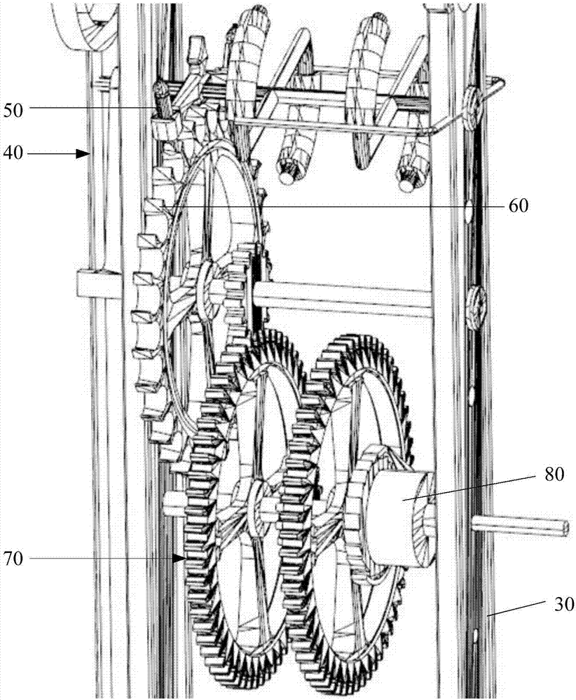
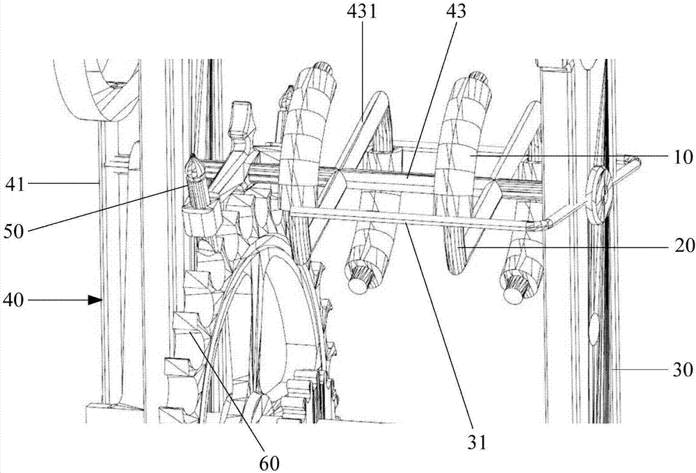
The invention discloses a power generation apparatus which includes an escapement mechanism and a power generation mechanism. The escapement mechanism includes a fixing frame and a vibration system which is in movable connection to the fixing frame. The power generation mechanism includes a coil and a magnetic member. The magnetic member is in fixed connection to the vibration system. The coil is in fixed connection to the fixing frame. The magnetic member extends to the coil and the magnetic member and the coil cooperate to perform axial reciprocating movement, such that by combining the escapement mechanism and the power generation mechanism, the power generation mechanism transforms kinetic energy generated by the escapement mechanism to electric energy, which achieves the purpose of power generation. Since the small escapement mechanism greatly reduces the size of the power generation apparatus, the power generation apparatus is much easier to carry, and the ongoing movement of the escapement mechanism and high rate of transformation contribute to high generation power. At the same time, since the manufacturing technology of the escapement mechanism is mature and stable, the implementation cost of the power generation apparatus is greatly reduced and the power generation apparatus is more stable.

Description

technical field [0001] The invention relates to the field of electronic technology, in particular to a power generating device. Background technique [0002] With the development of electronic technology, the functions of portable electronic devices are becoming more and more abundant, and people rely more and more on the electronic devices they carry with them in their daily life. However, due to the serious constraints of battery technology bottlenecks for a long time, the battery life of electronic devices has not been able to improve. When users are outdoors, they often worry that the power of electronic devices will run out, which seriously affects the user experience. [0003] In order to solve the above-mentioned problems, the prior art proposes a solution of using a power generating device to generate electricity to provide electric energy for electronic equipment. Some existing power generating devices use wind power, water power and other kinetic energy to drive t...

Claims


Application Information

Patent Timeline
Patent Type & Authority Applications(China)
IPC IPC(8): H02K7/18H02K35/02H02K35/04
CPCH02K7/1876H02K35/02H02K35/04Y02E10/30
Inventor 杜曦阳
Owner 杜曦阳
Why Eureka
Try Eureka