

High-precision peak current control method for switching power supply and circuits
A technology of peak current control and switching power supply, applied in control circuit and adjustment circuit, high-precision peak current control method of switching power supply, circuit field, can solve problems such as increasing chip pins, increasing circuit cost, and inability to accurately control, etc., to achieve High-precision control, the effect of improving the accuracy of the power supply
- Summary
- Abstract
- Description
- Claims
- Application Information
AI Technical Summary
Problems solved by technology
Method used
Image

Examples
Embodiment Construction
[0058] The present invention will be described in detail below in conjunction with the accompanying drawings.
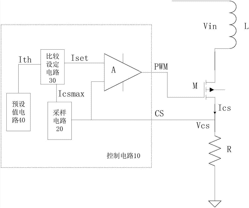
[0059] Such as figure 1 As shown, a switching power supply high-precision peak current circuit of the present invention includes: an inductance coil (L), a power tube (M), a sampling resistor (R) and a detection control circuit (10). The inductance coil (L), the power tube (M), and the sampling resistor (R) are connected in sequence, the sampling resistor (R) is grounded, the input end of the detection control circuit (10) is connected to the output end of the power tube (M), and the detection The output end of the control circuit (10) is connected to the control end of the power tube (M). The inductance coil (L) is a primary inductance coil.
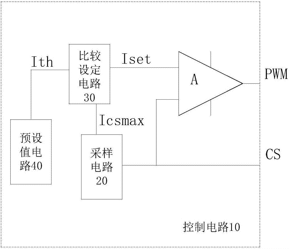
[0060] The detection control circuit (10) includes a sampling circuit (20), a comparison setting circuit (30), a preset value circuit (40) and a comparison circuit (A). The sampling circuit (20) is connected to the second i...
PUM
 Abstract
Description
Claims
Application Information