Road early-warning method based on vehicle-mounted blind zone camera

A lane departure warning and camera technology, applied to vehicle components, external condition input parameters, control devices, etc., can solve problems such as poor accuracy and susceptibility to interference, and achieve the goal of improving accuracy, high integration, and improving timeliness Effect

Active Publication Date: 2017-08-11
浙江华锐捷技术有限公司
View PDF5 Cites 38 Cited by
  • Summary
  • Abstract
  • Description
  • Claims
  • Application Information

AI Technical Summary

Problems solved by technology

[0005] The present invention mainly solves the technical problems of poor accuracy and susceptibility to interference in the prior art, and provides a road early warning method based on a vehicle-mounted blind spot camera with high accuracy and good robustness

Method used


Image

  • Road early-warning method based on vehicle-mounted blind zone camera
  • Road early-warning method based on vehicle-mounted blind zone camera
  • Road early-warning method based on vehicle-mounted blind zone camera

Examples


Embodiment

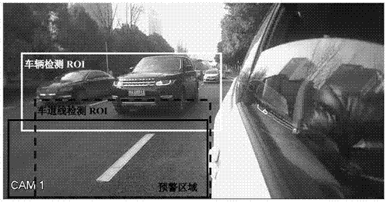
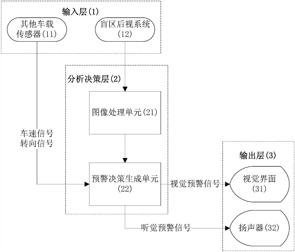
[0051] Embodiment: A kind of road early warning method based on the vehicle-mounted blind spot camera of this embodiment runs on the early warning system, such as figure 1 As shown, the early warning system includes an input layer 1, an analysis decision layer 2 and an output layer 3, the input layer includes a blind spot rear vision system 12 (blind spot camera) and other vehicle sensors 11, and the analysis decision layer includes an image processing unit 21 and an early warning decision generating unit 22. The output layer includes a visual interface 31 and a speaker 32. The image collected by the blind spot rear vision system is sent to the image processing unit, and after being processed by the image processing unit, it is sent to the early warning decision making unit. Other on-board sensors include sensors such as vehicle speed and steering wheel angle, and the detected information such as vehicle speed and steering wheel angle is sent to the early warning decision-maki...


PUM


Abstract

The invention discloses a road early-warning method based on a vehicle-mounted blind zone camera. The method comprises the following steps of detecting a vehicle running in the same direction in an adjacent lane by utilizing a vehicle-mounted blind zone vision system, judging the relative position and kinetic relation of the vehicle running in the same direction in the adjacent lane and a self vehicle, measuring the distance between the self vehicle and the current lane edge, and triggering an early-warning signal of a corresponding system according to the steering operation intention of a driver. When the driver has a steering intention, an early-warning signal is sent for a probable collision situation in a blind zone; and when the driver does not have the steering intention, an early-warning signal is sent for a yaw condition of the self vehicle. The system contains auxiliary driving functions related to lane change and lane keeping, the hardware cost is low, the timeliness is good, the integration level is high, and the safety performance of vehicles under medium and high speed working conditions in lane keeping and lane change can be effectively improved. The scheme is suitable for the field of vehicle aided driving.

Description

technical field [0001] The invention relates to the field of vehicle assisted driving, in particular to a road warning method based on a vehicle-mounted blind spot camera. Background technique [0002] Lane Change Warning System (LCW) and Lane Departure Warning System (LDW) are the main warning functions of vehicle assisted driving. The function of the former is to give an early warning of the existence of fast-moving vehicles in the blind spot of the vehicle when the driver has the intention to change lanes, so as to avoid the occurrence of potential lane-changing traffic accidents; Early warning of lane departure phenomenon in certain situations, so as to avoid the occurrence of potential lane change accidents or illegal driving behaviors (solid line lane change). Usually, the functions of the two systems are completed by different vision systems (LDW is realized by the forward-looking algorithm, and LCW is completed by the blind area algorithm). [0003] There are relat...

Claims


Application Information

Patent Timeline
Patent Type & Authority Applications(China)
IPC IPC(8): B60W30/08B60W30/095B60W50/14
CPCB60W30/08B60W30/0953B60W30/0956B60W50/14B60W2050/0043B60W2050/143B60W2050/146B60W2554/00
Inventor 缪其恒王江明许炜
Owner 浙江华锐捷技术有限公司
Why Eureka
Try Eureka