Storage device for grounding wire winding frames for power plant

A technology for storing devices and grounding wires, which is applied in storage devices, transportation, and packaging, and can solve unfavorable access to high-voltage short-circuit grounding wires and winding racks, increase the space occupied by grounding wire winding racks, and prevent high-voltage short-circuiting grounding wires. Damage and other problems, to facilitate recording and management, reduce collision deformation, and reduce friction

Inactive Publication Date: 2017-08-11
李晓旭
View PDF0 Cites 1 Cited by
  • Summary
  • Abstract
  • Description
  • Claims
  • Application Information

AI Technical Summary

Problems solved by technology

[0003] However, when the grounding wire winding frame is stored in the warehouse, it must be stored vertically. Usually, when the grounding wire winding frame is stored in the electric field, the grounding wire winding frame should be directly leaned against the wall or on the cross bar in the warehouse. , This storage method has two disadvantages: First, there is an angle between the grounding wire winding frame and the ground when storing in this way, and it is not placed vertically. Long-term storage will damage the high-voltage short-circuit grounding wire on the grounding wire winding frame. ; Second, it is placed out of order and takes up a lot of space. In power plants, high-voltage short-circuit grounding wires and grounding wire winding racks are commonly used safety equipment. According to different operating environments, different types of high-voltage short-circuit grounding wires are equipped, and the number is huge. , if the high-voltage short-circuit grounding wire and the winding frame are placed directly against the wall or in the warehouse, the space occupied by the large number of grounding wire winding frames will be increased, and the order will be disordered, which is not conducive to the high-voltage short-circuit grounding wire and winding rack access

Method used


Image

  • Storage device for grounding wire winding frames for power plant
  • Storage device for grounding wire winding frames for power plant
  • Storage device for grounding wire winding frames for power plant

Examples


Embodiment Construction

[0022] The present invention will be described in further detail below in conjunction with the accompanying drawings and specific embodiments. The specific embodiments described here are only used to explain the present invention, and are not intended to limit the content of the invention.

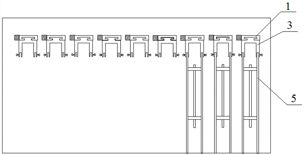
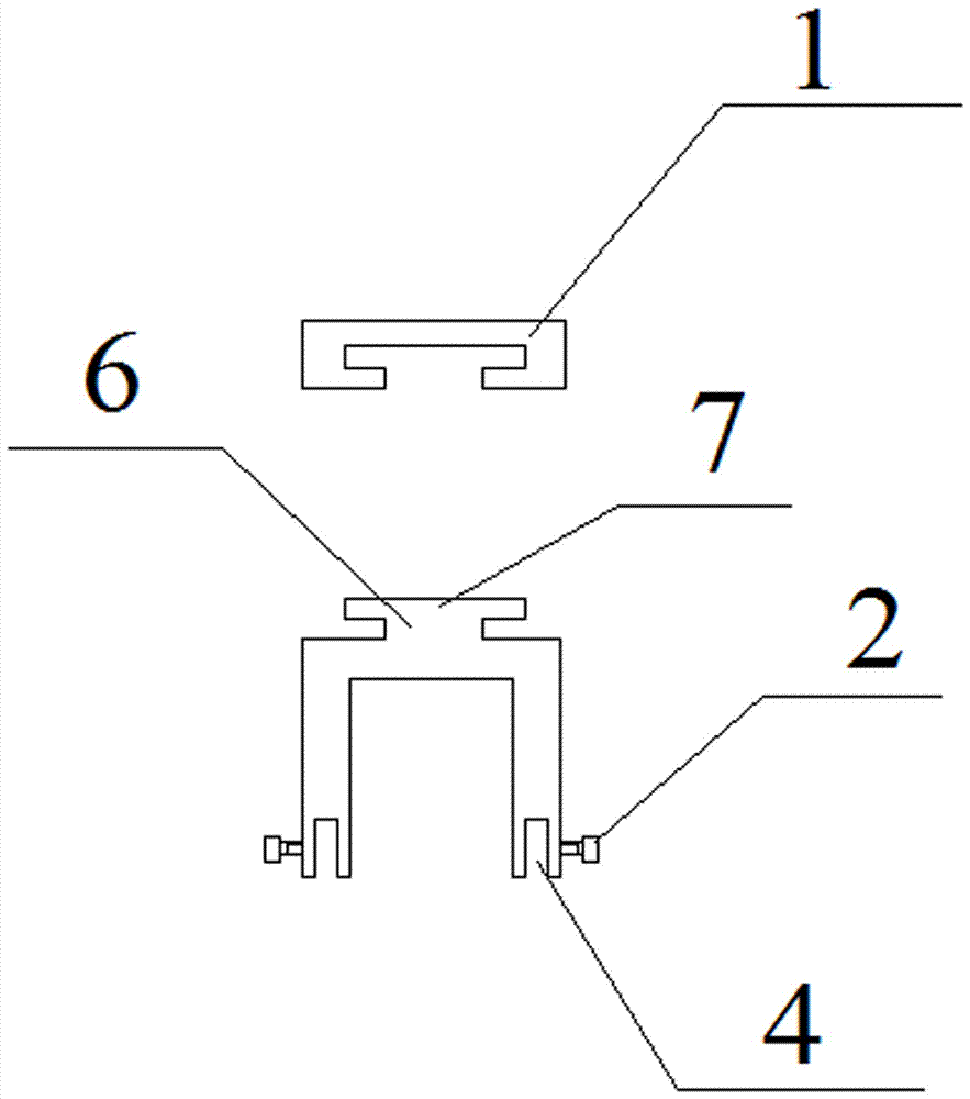
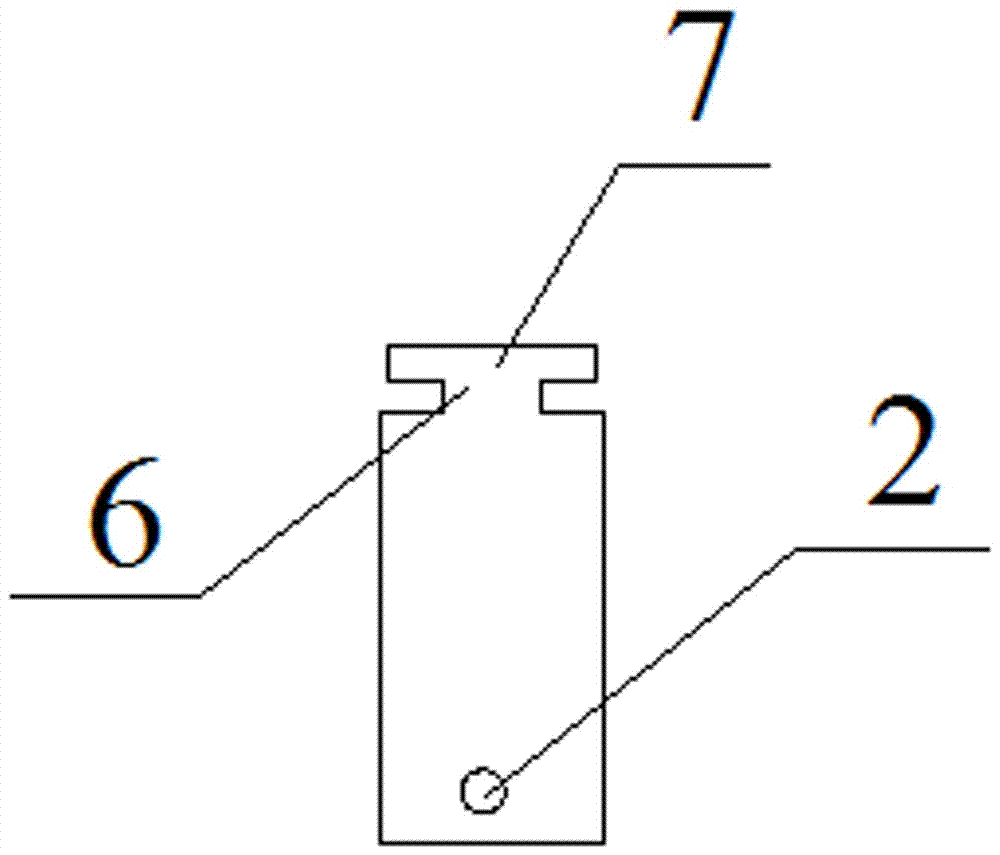
[0023] Such as figure 1 , 2 . 3 shows a storage device for a grounding wire winding frame for a power plant. The storage device includes a storage track 1 and a storage fixture 3. It is characterized in that: the storage track 1 is a plurality of side-by-side and downward openings. Concave guide rails, a plurality of concave guide rails are arranged at the same height and perpendicular to the wall, and the horizontal intervals between adjacent concave guide rails are the same; each concave guide rail is connected with a storage fixture 3, and the storage fixture 3 includes sliding mechanism and the clamping mechanism for clamping the grounding wire winding frame 5, the sliding mechanism ...


PUM


Abstract

The invention provides a storage device for a grounding wire winding frame used in a power plant. The storage device includes a storage track and a storage fixture. The guide rails are set at the same height and perpendicular to the wall; each concave guide rail is connected with a storage fixture, including a sliding mechanism and a clamping mechanism for clamping the grounding wire winding frame, and the sliding mechanism is slidably set in the concave guide rail , the clamping mechanism is connected to the lower end of the sliding mechanism, the clamping mechanism has a Π-shaped structure, and the end surface of the side wall is symmetrically provided with a rectangular chute, a clamping port and a clamping piece; the sliding mechanism is composed of a connecting plate and a sliding plate T-shaped structure, the sliding plate is located on the concave guide rail and can slide back and forth along the guide rail groove. The invention relates to a storage device for a grounding wire winding frame used in a power plant, which improves the inconvenience of storing and taking the grounding wire and the winding frame, saves space, is more concise and practical, and is easy to standardize management.

Description

technical field [0001] The invention relates to a storage device, in particular to a storage device for a winding frame of a high-voltage short-circuit grounding wire used in a power plant. Background technique [0002] The high-voltage short-circuit grounding wire is a commonly used protection device in the field of electric power. It is used to prevent electrostatic induction electric shocks near the charged body or to ensure safety when closing the switch by mistake. It is made of twisted strands of high-quality copper wire. The common structures of grounding wire winding frames include vertical frames, hanging rods, beams, etc., and their materials are mostly hollow metal tubes, which are not only easy to process, but also can save materials. In specific use, a group of grounding wires are wound and hung on a winding frame. [0003] However, when the grounding wire winding frame is stored in the warehouse, it must be stored vertically. Usually, when the grounding wire ...

Claims


Application Information

Patent Timeline
Patent Type & Authority Applications(China)
IPC IPC(8): B65G1/04
CPCB65G1/0457
Inventor 李晓旭
Owner 李晓旭
Why Eureka
Try Eureka