Safety lock used for aloft work device and using method of safety lock

A technology for working at heights and safety locks, which is applied to lifting devices, safety devices of lifting equipment, etc., can solve the problems of complex safety lock structure, complex internal structure, low reliability, etc., so as to ensure the safety of working at heights and personnel, avoid Potential safety hazards, ease of installation and use

Pending Publication Date: 2017-08-11
周勇华
View PDF8 Cites 1 Cited by
  • Summary
  • Abstract
  • Description
  • Claims
  • Application Information

AI Technical Summary

Problems solved by technology

The internal structures of these two kinds of safety locks are relatively complicated, including a large number of return springs and bearings. Therefore, the failure rate is high and the reliability is low. Falling impurities will cause the lock body to be stuck, and emergency braking cannot be performed at critical moments, losing the safety protection function; moreover, the calibers of these two safety locks are usually fixed, and must be installed on the matching sling to be able to To play a role, a sling that is too thin cannot be locked, and a sling that is too thick cannot pass through the lock body. The versatility is not strong, and installation and maintenance are inconvenient
[0003] The existing technology that is closer to the present invention is the invention patent N

Method used


Image

  • Safety lock used for aloft work device and using method of safety lock
  • Safety lock used for aloft work device and using method of safety lock
  • Safety lock used for aloft work device and using method of safety lock

Examples


Example Embodiment

[0033] The following describes the present invention in further detail with reference to the drawings and specific embodiments, but the present invention is not limited to this embodiment:
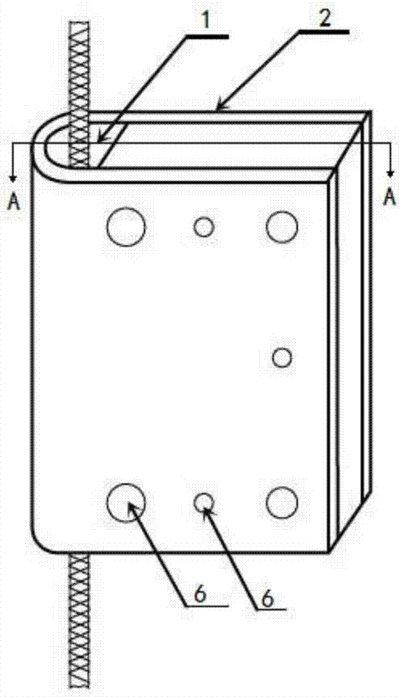
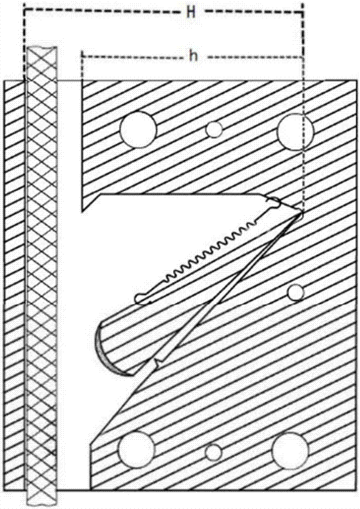
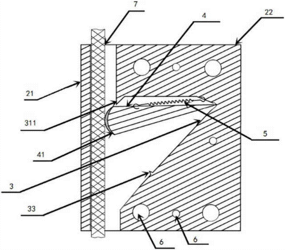
[0034] A safety lock for high-altitude operation devices, including:

[0035] A lock body 2 having a vertical through hole 1 and a groove 3, the outer side of the vertical through hole 1 is the lock shell 21 and the inner side is the lock core 22, the groove 3 is provided on the side of the lock core 22, the groove 3 The inner cavity is provided with a pendulum 4 and an elastic element 5; the groove 3 includes a waterproof chamfer 311, an upper groove 312, a spring fixing surface 313, and a groove inclined surface 314 to form a cavity of a V-shaped groove 3, so The intersection of the spring fixing surface 313 and the groove slope 314 is rounded, the swing fulcrum of the pendulum 4 is located in the rounded corner, one end of the elastic element 5 is fixed on the spring fixing surface 313 and t...


PUM

PropertyMeasurementUnit
Plane angleaaaaaaaaaa

Abstract

The invention provides a safety lock used for an aloft work device and a using method of the safety lock. The safety lock used for the aloft work device comprises a lock body provided with a vertical through hole and a groove. A lock case is arranged outside the vertical through hole, and a lock cylinder is arranged inside the vertical through hole. The groove is formed in the lock cylinder side. A pendulum bob and an elastic element are arranged in an inner cavity of the groove. The groove comprises a V-shaped groove cavity which is formed by a waterproof chamfer, an upper groove plane, a spring fixing face and an oblique groove plane in an enclosure mode, the junction of the spring fixing face and the oblique groove plane is a fillet, and the end, with the swinging fulcrum, of the pendulum bob is located in the fillet. The safety lock provided by the invention is simple in structure; and through the design of the V-shaped groove structure and the waterproof chamfer and the protrusion design of the oblique plane, accumulation of water and dust residues can be effectively prevented, potential safety hazards, caused by erosion of water vapor and dust, of the safety lock are avoided fundamentally, the service life of the safety lock is prolonged greatly, frequent inspection and maintenance are not needed, and effective braking and locking functions can be ensured.

Description

technical field [0001] The invention belongs to a safety protection device. The invention specifically relates to a safety lock for a high-altitude operation device, and belongs to the technical field of high-altitude operation safety protection. Background technique [0002] Serious accidents of high-altitude operations include the sudden and rapid fall of high-altitude operation devices. Once such accidents occur, the consequences will be disastrous. Therefore, preventing the sudden fall of the high-altitude operation device is the basic requirement to ensure the safety of high-altitude operations, and relevant safety precautions have become necessary equipment for high-altitude operations, and safety locks are one of them. At present, there are two main types of safety locks used for high-altitude operations at home and abroad: swing arm type and centrifugal type. The internal structures of these two kinds of safety locks are relatively complicated, including a large num...

Claims


Application Information

Patent Timeline
IPC IPC(8): B66F11/04B66F17/00
CPCB66F11/04B66F17/006
Inventor 周勇华
Owner 周勇华
Why Eureka
Try Eureka