Prestressed anchorage device with replaceable anchorage and construction method of installation and cable replacement thereof

An anchoring device and construction method technology, applied in bridge reinforcement, erection/assembly of bridges, construction, etc., can solve problems such as inability to change directions, inapplicability, etc., and achieve the effects of convenient cable replacement, cost saving, and high efficiency

Pending Publication Date: 2017-08-11
LIUZHOU OVM MACHINERY
View PDF7 Cites 2 Cited by
  • Summary
  • Abstract
  • Description
  • Claims
  • Application Information

AI Technical Summary

Problems solved by technology

[0008] In order to solve the above problems, the applicant has successively applied for a patent publication number of CN104372738A, and the title of the invention is "A Single Interchangeable Anchor Prestressed Anchoring Device and Its Installation and Cable Replacement Construction Method", and the patent publication number is CN104947589A. Two invention patent applications named "Multi-Strand Finished Cable Anchor Prestressed Anchorage Device and Its Construction Method" have the following disadvantages: the pre-embedded pipes are all straight pre-embedded pipes, which are not suitable fo

Method used


Image

  • Prestressed anchorage device with replaceable anchorage and construction method of installation and cable replacement thereof
  • Prestressed anchorage device with replaceable anchorage and construction method of installation and cable replacement thereof
  • Prestressed anchorage device with replaceable anchorage and construction method of installation and cable replacement thereof

Examples


Example Embodiment

[0049] Embodiment one:

[0050] A replaceable anchor prestressed anchoring device:

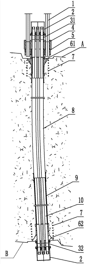
[0051] like figure 1 As shown, the replaceable anchorage prestressed anchoring device includes a prestressed concrete anchoring part and a main cable strand connecting part for connecting with the main cable strand. The main cable strand connecting part includes a pull rod 1, a protective Cover 2, front support plate 31, rear support plate 32, connector 4 and nut assembly 5; the prestressed concrete anchoring part includes a pre-embedded assembly embedded in the concrete, anchor strands, and the pre-embedded assembly includes The upper anchor backing plate 61, the lower anchor backing plate 62, the spiral reinforcement 7 and the pre-embedded pipe, the anchor strands are finished cables 10 that have been processed in the factory, and there is no anti-corrosion material in the pre-embedded pipe of the pre-embedded components;

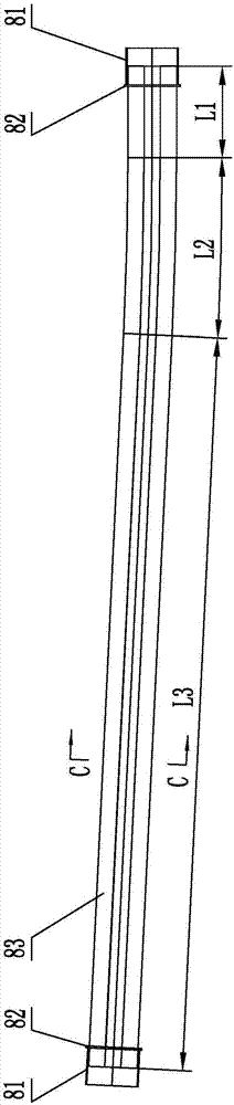
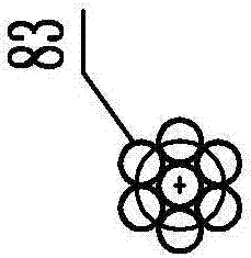
[0052] like Figure 2-1~Figure 2-1 As shown, the pre-embedded pip...

Example Embodiment

[0055] Embodiment two:

[0056] A method of installation and construction of a replaceable anchorage prestressed anchorage device:

[0057] It is an installation and construction method of a replaceable anchorage prestressed anchoring device described in Embodiment 1 of the present invention, including the following steps:

[0058] Step 1: Embedded parts installation: pre-embed the lower anchor plate 62, spiral reinforcement 7, straight embedded pipe 9, split-wire steering embedded pipe 8, and upper anchor plate 61 on site, pour concrete in layers and then cure until design strength;

[0059] Step 2: Connector installation: install and fix the connector 4 on the end face of the upper anchor plate 61 with bolts at the upper end;

[0060] Step 3: Anchor Strand Installation:

[0061] Step 3-1: Finished cable installation: Put the finished cable 10 that has been prepared in the factory through the front support plate 31, the connector 4, the upper anchor plate 61, and the split...

Example Embodiment

[0067] Embodiment three:

[0068] A method for changing cables of a replaceable anchorage prestressed anchorage device, which is a method for changing cables of the replaceable anchorage prestressed anchorage device described in Embodiment 1 of the present invention, comprising the following steps:

[0069] Step 1: Remove the protective cover: remove the upper and lower protective cover 2;

[0070] Step 2: unloading of the old finished cables: use devices such as jacks, braces, and tension rods at the lower end to tension and loosen any one of the finished cables 10;

[0071] Step 3: Remove the old finished cable: connect the old cable with an index cable on the rear anchor surface / front anchor surface, pull out an unloaded old finished cable 10 from the tunnel on the front anchor surface / rear anchor surface, and remove it;

[0072] Step 4: installation of the new finished cable: connect the new cable with a traction cable on the front anchor surface / rear anchor surface, and ...


PUM


Abstract

The invention discloses a prestressed anchorage device with a replaceable anchorage. The device comprises a prestressed concrete anchorage part and a main cable strand connecting part used for being connected with a main cable strand. The prestressed concrete anchorage part comprises an embedded assembly and an anchorage cable strand, wherein the embedded assembly is composed of upper-end anchor backing plates, lower-end anchor backing plates, spiral bars and an embedded pipe. The embedded pipe comprises a separating diversion embedded pipe and a straight embedded pipe, wherein the separating diversion embedded pipe is formed by assembly welding of connecting pipes, round plates and n crooked steel pipes, and the separating diversion embedded pipe is connected with the upper-end anchor backing plates and the straight embedded pipe through the connecting pipes and the round plates at both ends respectively; n is an integer which is equal to or greater than 2 and less than or equal to 100. By means of the prestressed anchorage device with the replaceable anchorage, the defects of common prestressed anchorage devices of suspension bridge tunnel-type anchorages can be effectively overcome, anchorage is reliable, corrosion protection is superior, construction and monitoring are easy and convenient, replacement of multiple strands of finished cables can be conveniently achieved in the condition that operation of a bridge is not influenced, and thus the prestressed anchorage device with the replaceable anchorage is especially suitable for a tunnel-type anchorage system with a crooked channel.

Description

technical field [0001] The invention relates to a prestressed anchoring system, in particular to a replaceable anchorage prestressed anchoring device and a construction method for installing and changing cables. Background technique [0002] The anchorage system of large suspension bridges mostly adopts prestressed anchorage system. There are two types of prestressed anchorage systems commonly used in tunnel anchorage. One is the bonded anchorage system in which grout is poured into the prestressed tunnel. , one is a non-bonding single replaceable anchoring system in which anti-corrosion grease is poured into the prestressed channel. The length of the large-scale tunnel-type anchorage concrete body is generally long. The prestressed channels in the above two types of anchorage systems are generally provided with curved sections, and the direction of each prestressed beam is changed through the curved section to reduce the prestressed beams. The divergent size in the anchor ...

Claims


Application Information

Patent Timeline
IPC IPC(8): E01D19/14E01D21/00E01D22/00
CPCE01D19/14E01D21/00E01D22/00
Inventor 陈克坚苏强艾智能谢正元许智焰吴东明王耀冯新宽
Owner LIUZHOU OVM MACHINERY
Why Eureka
Try Eureka