Engine brake oil way control device and usage method thereof

A technology for engine braking and control devices, which is applied in the direction of engine control, engine components, machines/engines, etc., can solve the problems of high manufacturing accuracy, poor braking effect, and high production cost, and achieve high manufacturing accuracy requirements, less error, and The effect of low production cost

Active Publication Date: 2017-08-11
DONGFENG COMML VEHICLE CO LTD
View PDF6 Cites 5 Cited by
  • Summary
  • Abstract
  • Description
  • Claims
  • Application Information

AI Technical Summary

Problems solved by technology

[0006] The purpose of the present invention is to overcome the defects and problems of poor braking effect, high manufacturing precision and high production cost existing in the prio

Method used


Image

  • Engine brake oil way control device and usage method thereof
  • Engine brake oil way control device and usage method thereof
  • Engine brake oil way control device and usage method thereof

Examples


Embodiment 1

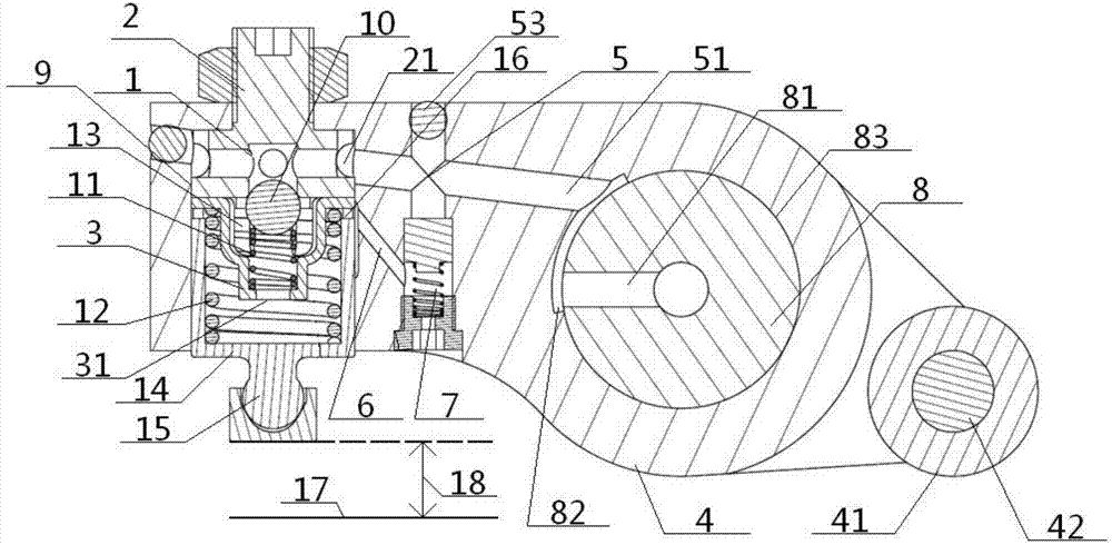
[0059] see Figure 1 to Figure 9, an engine brake oil circuit control device, including a rocker arm 4 and a brake actuator 1 set on it, a rocker arm shaft 8 and a rocker arm roller 41, and the rocker arm shaft 8 passes through the brake oil circuit 5 It communicates with the brake actuator 1, and the side of the brake actuator 1 communicates with the oil discharge passage 6. The interior of the brake actuator 1 is provided with a brake piston 14 that moves up and down along its axial direction, and the bottom of the brake piston 14 It is connected with the elephant foot 15 directly below it, and a valve gap 18 is formed between the bottom of the ball socket 152 in the elephant foot 15 and the valve yoke 17 directly below it;

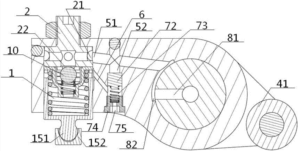
[0060] The engine brake oil circuit control device also includes a control valve 7 arranged inside the rocker arm 4. The control valve 7 includes a control chamber 71 and a control piston 72, a control spring 73, and a control chamber arranged in sequen...

Embodiment 2

[0064] Basic content is the same as embodiment 1, the difference is:

[0065] The method of use also includes an operating process under braking conditions. The operating process under braking conditions includes the following steps in sequence: under braking conditions, the pressure of the oil entering the brake oil circuit 5 through the rocker shaft 8 is greater than that of the control spring 73 spring force, the engine oil entering the longitudinal oil passage 52 continuously compresses the control spring 73 until the descending control piston 72 blocks the oil discharge passage 6 so that the oil in the oil discharge passage 6 no longer enters the control chamber 71. At this time, the inclined The machine oil flowing into the brake oil chamber 13 from the oil passage 51 no longer flows out through the unloading oil passage 6, and the brake oil chamber 13 forms a closed chamber. When the machine oil continues to enter, the ball socket 152 in the elephant foot 15 is driven by...

Embodiment 3

[0067] Basic content is the same as embodiment 2, the difference is:

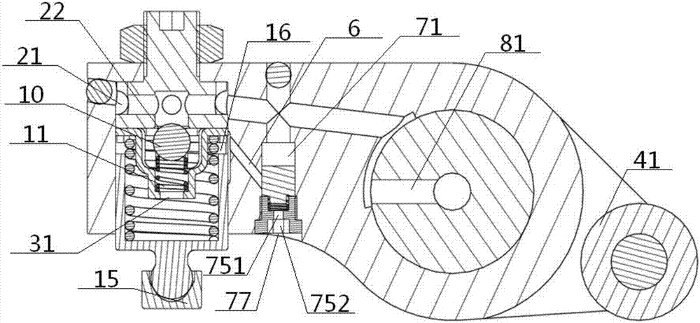
[0068] The brake actuator 1 includes a brake chamber 9, an adjusting bolt 2, a ball valve 10, a ball valve spring 11, a ball valve spring seat 3, a brake spring 12, a brake oil chamber 13, a brake piston 14 and an elephant foot 15. The bottom end of the adjustment bolt 2 is located inside the brake chamber 9, and the top end of the adjustment bolt 2 passes through the brake chamber 9 and the rocker arm 4 in sequence and is fixedly connected with the outer wall of the rocker arm 4 (preferably, the top end of the adjustment bolt 2 is adjusted by adjusting The nut 23 is fixedly connected with the outer wall of the rocker arm 4), the side and the bottom surface of the bottom of the adjustment bolt 2 are provided with corresponding side oil holes 21 and bottom surface oil holes 22 respectively, and the high port of the oblique oil passage 51 passes through the side oil holes 21 It communicates with the oil hole ...


PUM

PropertyMeasurementUnit
Radianaaaaaaaaaa

Abstract

An engine brake oil way control device comprises a rocker, a brake performing mechanism, a control valve, a slant oil way and a longitudinal oil way. The brake performing mechanism and the control valve are arranged on the rocker. The slant oil way and the longitudinal oil way intersect. A control piston, a control spring and a control spring seat are arranged in the control valve sequentially from top to bottom. A control oil discharge hole is formed in the control spring seat. The part, located between the control piston and the control spring seat, on the side wall of a control chamber communicates with the side part of a brake oil cavity through an oil discharge way. The top end of the control chamber communicates with the bottom of the longitudinal oil way. The top of the longitudinal oil way penetrates through the slant oil way and then extends to be above the slant oil way, and a shaft-in oil way of a rocker shaft communicates with the brake oil cavity in the brake performing mechanism through the slant oil way. During usage, opening or closing of the oil discharge way is achieved through change of engine oil pressure by means of the control valve, and thus the brake condition is started or relieved. Therefore, the engine brake oil way control device is good in brake effect, high in stability, good in clearance adjustment effect, low in production cost, and capable of lowering noise during mechanism operation.

Description

technical field [0001] The invention relates to an oil circuit control device, which belongs to the technical field of vehicle engine braking, in particular to an engine brake oil circuit control device and a method of use thereof, which are particularly suitable for enhancing the control effect of the brake oil circuit and simplifying its structure . Background technique [0002] The engine braking system is an in-cylinder braking technology of a diesel engine, which is generally of the compression release type. One or two exhaust valves are hydraulically driven to open at the end of the engine compression stroke. Friction and intake and exhaust resistance form a braking technology. Compression release brakes are generally implemented in three ways: external type, special rocker type, and integrated rocker type. A set of hydraulic components is used to cooperate with oil on-off or oil pressure changes to realize the formation of high-pressure oil chambers for brake pistons...

Claims


Application Information

Patent Timeline
IPC IPC(8): F01L13/06F02D13/04F01L1/20
CPCF01L1/20F01L13/06F02D13/04F01L2760/003F01L2810/04
Inventor 张芳万虎吴囿霖廖显敏
Owner DONGFENG COMML VEHICLE CO LTD
Why Eureka
Try Eureka