
Sheet and ladder type air distribution device for circulating fluidized bed boiler

A circulating fluidized bed and air distribution device technology, applied in the field of waste incinerators, can solve the problems of aggravated flow field disorder, impact wear, difficult discharge, etc., to achieve improved fluidization uniformity, strong directional blowing ability, and improved impact wear effect

Active Publication Date: 2017-08-11
TSINGHUA UNIV
View PDF5 Cites 0 Cited by
  • Summary
  • Abstract
  • Description
  • Claims
  • Application Information

AI Technical Summary

Problems solved by technology

When circulating fluidized bed technology is applied to waste treatment, the horizontally arranged air distribution boards have exposed its shortcomings: due to the complex composition of urban waste, the bed materials have large differences in particle size and density, and some large and heavy particles are deposited on the air distribution boards. It is difficult to discharge, which greatly reduces the uniformity and stability of the flow in the bed, and even causes a non-fluidized state at the bottom
[0004] During the operation of the boiler, it was found that when the "Γ"-shaped directional air cap is used, the wear phenomenon is very serious. The boiler operation cycle is shortened, which not only increases the boiler operation cost, but also seriously affects the safety of the boiler operation
Through the inspection of the air cap and the observation of the damaged air cap every time the boiler is shut down, it is found that the top of the air cap is severely worn. This is due to the installation design of the "Γ"-shaped directional air cap, and the high-speed wind coming out of the rear air cap entrains the bed material. The top of the front hood is directly blown to form impact wear. With the extension of the running time, the high-speed wind carrying a large number of particles will "cut" the top and body of the front hood to form a jet, which further intensifies the flow field. Disturbance not only affects the fluidization quality, but also accelerates the wear of the air cap, affecting the safety and efficiency of boiler operation

Method used


Image

  • Sheet and ladder type air distribution device for circulating fluidized bed boiler
  • Sheet and ladder type air distribution device for circulating fluidized bed boiler
  • Sheet and ladder type air distribution device for circulating fluidized bed boiler

Examples


Embodiment Construction

[0021] The principle, specific structure and implementation of the present invention will be further described below in conjunction with the accompanying drawings.

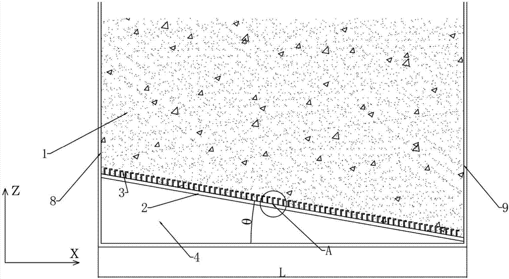
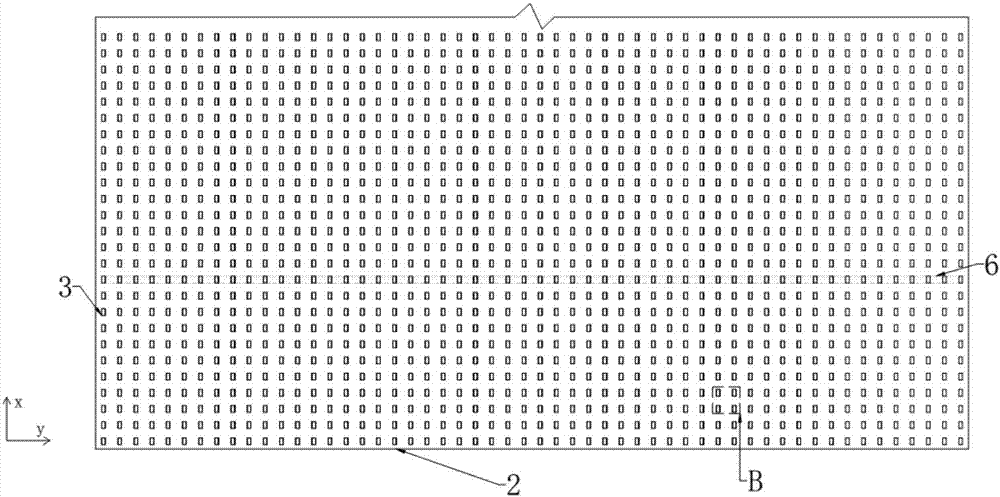
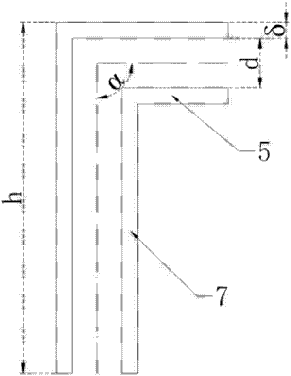
[0022] figure 1 It is a structural schematic diagram of a sheet-shaped stepped air distribution device for a circulating fluidized bed boiler of the present invention, figure 2 It is a top view of the inclined air distribution plate with "Γ"-shaped directional air caps, which shows that the "Γ"-shaped directional air caps 3 are stepped in the height direction and sheet-shaped in the horizontal direction. The air distribution device includes an air chamber 4, an inclined air distribution plate 2 and a "Γ"-shaped directional air cap 3 arranged on the inclined air distribution plate 2, and the "Γ"-shaped directional air cap main air duct 7 is installed vertically on the On the inclined air distribution board 2; the same row of "Γ"-shaped directional air caps 3 are on a straight line, showing a sheet structure, and ...


PUM


Abstract

The invention relates to a sheet and ladder type air distribution device for a circulating fluidized bed boiler, and belongs to the technical field of air supply and auxiliary equipment of a circulating fluidized bed boiler; the air distribution device comprises an inclined air distribution plate and inverted L-shaped directional air caps; the main air pipe of each of the inverted L-shaped directional air caps is vertically mounted on the inclined air distribution plate; the inverted L-shaped directional air caps are distributed on the inclined air distribution plate in the form of a two-dimensional array; researches show that the horizontal distance between every two adjacent rows of inverted L-shaped directional air caps in the descent direction of the inclined air distribution plate and the included angle between the outlet direction of each of jet pipes and the descent direction of the inclined air distribution plate satisfy a certain function relationship. With the adoption of the air distribution structure, that high speed air ejected from the jet pipe of each of the back row of inverted L-shaped directional air caps can blow over the tops of the front row of inverted L-shaped directional air caps is ensured, the impact and abrasion of the back row of inverted L-shaped directional air caps to the front row of inverted L-shaped directional air caps are avoided, the using time of the inverted L-shaped directional air caps is increased, the operation cycle of the boiler is prolonged, and the economical efficiency and safety of the circulating fluidized bed boiler are improved.

Description

technical field [0001] The present invention relates to an air distribution method and an air distribution device in a circulating fluidized bed boiler furnace, especially to a garbage incinerator. Technical and auxiliary equipment field. Background technique [0002] In recent years, with the increase of population and the improvement of people's living standards, the amount of garbage generated every day is also increasing. If these garbage cannot be disposed of in time, it will cause great harm to human beings and the environment. At present, there are three relatively mature treatment methods: landfill, incineration and biological treatment. The incineration method is favored due to a series of advantages such as high degree of harmlessness, large capacity reduction, heat recovery, and timely treatment. Both foreign and domestic waste incineration technologies are quite mature, mainly represented by grate furnace, fluidized bed and rotary drum incinerator. Among them...

Claims


Application Information

Patent Timeline
IPC IPC(8): F23C10/20
CPCF23C10/20F23C2206/10
Inventor 张贤葛荣存蔡润夏张缦杨海瑞吕俊复吴玉新张海
Owner TSINGHUA UNIV
Learn More