Heat-recovery air-cooling heat pump drying system applicable to large temperature difference

An air-cooled heat pump and drying system technology, applied in heat recovery system, heat pump, drying and other directions, can solve the problems of unavailability of moisture exhaust waste heat, single drying method, serious environmental pollution, etc., and achieves ingenious design optimization of the unit, The effect of broadening the application field and improving the dehumidification energy consumption ratio

Active Publication Date: 2017-08-11
ZHONGYUAN ENGINEERING COLLEGE
View PDF8 Cites 6 Cited by
  • Summary
  • Abstract
  • Description
  • Claims
  • Application Information

AI Technical Summary

Problems solved by technology

[0004] The technical problem to be solved by the present invention is that in the existing drying process, the environmental pollution is serious, the energy consumption of dehumidification is relatively low, the operating cost is high, the drying method is single, and the waste heat of dehumidification cannot be used, and a heat recovery type suitable for large temperature difference is provided. Air-cooled heat pump drying system

Method used


Image

  • Heat-recovery air-cooling heat pump drying system applicable to large temperature difference
  • Heat-recovery air-cooling heat pump drying system applicable to large temperature difference
  • Heat-recovery air-cooling heat pump drying system applicable to large temperature difference

Examples


Embodiment Construction

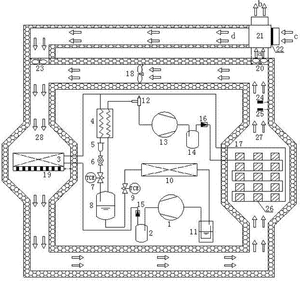
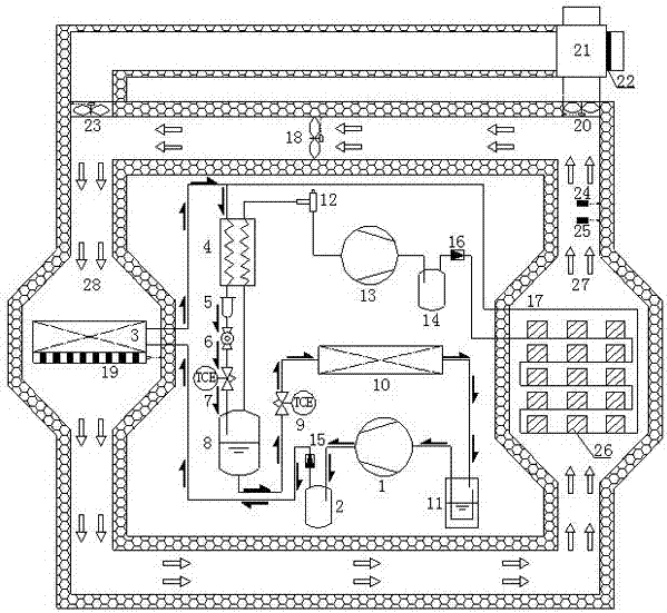
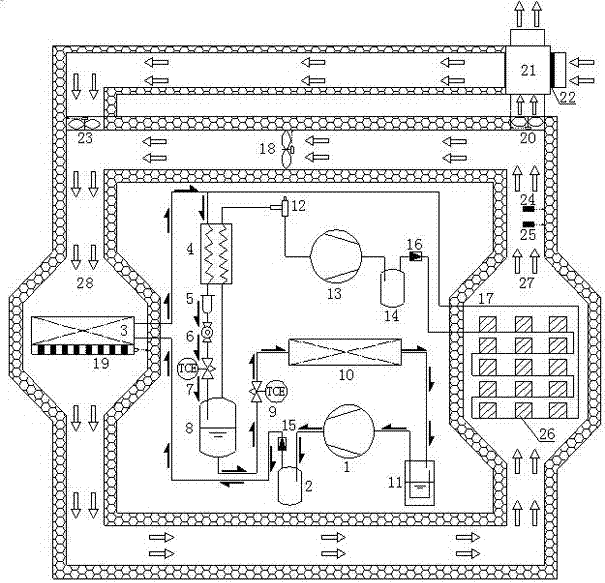
[0027] Such as figure 1 As shown, the present invention includes a three-pressure air-cooled heat pump subsystem and a drying medium circulation subsystem. The three-pressure air-cooled heat pump subsystem includes a main road compressor 1, a main road oil separator 2, and a main road condenser 3 , recooler 4, medium-pressure gas-liquid separator 8, evaporator 10, low-pressure gas-liquid separator 11, auxiliary circuit compressor 13, auxiliary circuit oil separator 14 and auxiliary circuit condenser 17, the discharge of the main circuit compressor 1 The gas port is connected with the inlet of the main road condenser 3 through the main road oil separator 2; the outlet of the main road condenser 3 is connected with the main road inlet of the recooler 4 and the outlet of the auxiliary road condenser 17 respectively; The outlet of the main path of the subcooler 4 is connected to the inlet of the medium-pressure gas-liquid separator 8; the two outlets of the medium-pressure gas-liq...


PUM


Abstract

The invention discloses a heat-recovery air-cooling heat pump drying system applicable to a large temperature difference, for solving the technical problems of serious environment pollution, low dehumidification energy consumption, high running cost, single drying manner and incapacity of utilizing dehumidification waste heat in an existing drying process. The heat-recovery air-cooling heat pump drying system disclosed by the invention comprises a three-pressure air-cooling heat pump sub-system and a drying medium circulation sub-system, wherein the three-pressure air-cooling heat pump sub-system comprises a main-channel compressor, a main-channel oil separator, a main-channel condenser, an aftercooler, a medium-pressure gas-liquid separator, an evaporator, a low-pressure gas-liquid separator, an auxiliary-channel compressor, an auxiliary-channel oil separator and an auxiliary-channel condenser, and the exhaust port of the main-channel compressor is connected with the inlet of the main-channel condenser; and the exhaust port of the auxiliary-channel compressor is connected with the inlet of the auxiliary-channel condenser through the auxiliary-channel oil separator. After adopting the technical scheme, the reliability, stability and economical efficiency of the annual running of the air-cooling heat pump drying system disclosed by the invention are improved, and the application field is expanded.

Description

technical field [0001] The invention relates to the technical field of heat pump drying, in particular to a heat recovery type air-cooled heat pump drying system suitable for large temperature differences. Background technique [0002] Facing the increasingly prominent problems of energy shortage and environmental pollution, traditional drying technologies such as oil, gas, coal or wood have been gradually eliminated. At present, there are two main environmental protection drying technologies commonly used. One is the use of electric heating tubes. Direct heating technology is easy to operate, but the efficiency is too low and the operating cost is high, which is contrary to the national energy-saving policy; the other is to use heat pump drying technology, especially air source heat pump technology, which has simple structure, convenient installation and use, energy saving and environmental protection , some enterprises have begun to use it. However, the current convention...

Claims


Application Information

Patent Timeline
Patent Type & Authority Applications(China)
IPC IPC(8): F26B9/06F25B30/02F26B23/10F25B43/00F26B23/06F26B25/00F25B41/06F26B21/00F26B21/08F26B21/10F25B41/04F25B41/20F25B41/31
CPCF25B30/02F25B43/006F26B9/06F26B21/003F26B21/08F26B21/10F26B23/06F26B23/10F26B25/00F25B41/22F25B41/31Y02B30/70
Inventor 刘寅崔四齐马静刘恩海于海龙酒曼张艳李悦
Owner ZHONGYUAN ENGINEERING COLLEGE
Why Eureka
Try Eureka