Tensile-resistant test device for digital display missile antenna

A test device, digital display technology, applied in the direction of measuring device, using stable tension/pressure test material strength, instrument, etc., can solve problems such as easy breakage, and achieve the effect of overcoming easy breakage, convenient placement, and convenient adsorption

Inactive Publication Date: 2017-08-11
KUNSHAN SHANSHAN PLASTIC TECH CO LTD
View PDF6 Cites 0 Cited by
  • Summary
  • Abstract
  • Description
  • Claims
  • Application Information

AI Technical Summary

Problems solved by technology

However, when the current tensile test device used for ultra-thin products of high-end equipment is in use, there will be a problem that it will be easily broken during the process of tensile test due to improper operation during the adsorption process. Therefore, a digital display missile is proposed to solve the above problems. Antenna tensile testing device

Method used


Image

  • Tensile-resistant test device for digital display missile antenna
  • Tensile-resistant test device for digital display missile antenna

Examples


Embodiment Construction

[0015] The following will clearly and completely describe the technical solutions in the embodiments of the present invention with reference to the accompanying drawings in the embodiments of the present invention. Obviously, the described embodiments are only some, not all, embodiments of the present invention. Based on the embodiments of the present invention, all other embodiments obtained by persons of ordinary skill in the art without making creative efforts belong to the protection scope of the present invention.

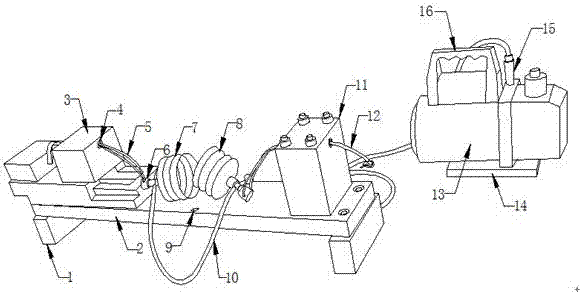
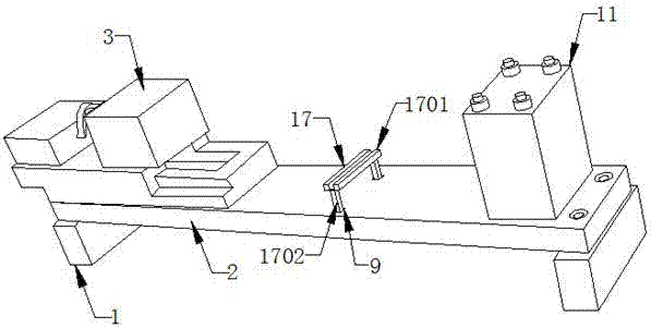
[0016] see Figure 1-2 As shown, the tensile test device of the digital display type missile antenna includes a workbench 2, on which a first test bench 3 is arranged; one side of the first test bench 3 is provided with a through hole 4; the through hole 4 is connected There is a pull wire 5; the pull wire 5 is wound on the connector 6; one side of the connector 6 is connected to the first plastic sucker 7; the first plastic sucker 7 is conical, and one side o...


PUM


Abstract

The invention discloses a tensile-resistant test device for a digital display missile antenna. The tensile-resistant test device comprises a supporting block, a working table, a first test table, a through hole, a drawing wire, a connector, a first plastic sucker, a second plastic sucker, an inserting hole, an air pipe, a second test table, a connecting wire, a vacuum pump, a base, an air pipe connecting end, a handle, a product placing part, a groove block and a fine column. The tensile-resistant test device has the advantages that products to be tested are conveniently placed by the product placing part of tensile-resistant test device of thin products for high-end devices, the product placing part is formed by the groove block and the fine column, inserting products to be tested can be effectively clamped by the groove block, so that the products to be tested can be conveniently and effectively adsorbed by the first plastic sucker and the second plastic sucker, and the product placing part can be conveniently taken out from the inserting hole of the working table and the products after the products to be tested are adsorbed, so that subsequent operations are performed.

Description

technical field [0001] The invention relates to the field of guidance receiving devices, in particular to a guidance antenna with high strength and high and low temperature resistance. Background technique [0002] The technology and method of guiding and controlling the aircraft to fly to the target or predetermined orbit according to certain rules is called guidance. During the guidance process, the guidance system continuously measures the relative positional relationship between the aircraft and the target or the predetermined orbit, and sends guidance information to the aircraft control system to control the flight. Divided into wired guidance, radio guidance, radar guidance, infrared guidance, laser guidance, audio guidance, geomagnetic guidance, inertial guidance and astronomical guidance. Among them, most of the guidance methods require a method involving signal transmission and signal reception. The device installed on the aircraft for signal reception is generally...

Claims


Application Information

Patent Timeline
Patent Type & Authority Applications(China)
IPC IPC(8): G01N3/08
CPCG01N3/08G01N2203/0017
Inventor 倪进
Owner KUNSHAN SHANSHAN PLASTIC TECH CO LTD
Why Eureka
Try Eureka