
CT (computer tomography) real-time three-dimensional scanning seepage and shear coupling rock triaxial test system

A triaxial test, real-time three-dimensional technology, applied in the direction of using stable shear force to test material strength, using stable tension/pressure test material strength, permeability/surface area analysis, etc., can solve the effect of shear consideration , seepage, confining pressure of rock specimens, etc., to achieve the effect of ensuring strength

Pending Publication Date: 2017-08-11
SHAOXING UNIVERSITY
View PDF7 Cites 11 Cited by
  • Summary
  • Abstract
  • Description
  • Claims
  • Application Information

AI Technical Summary

Problems solved by technology

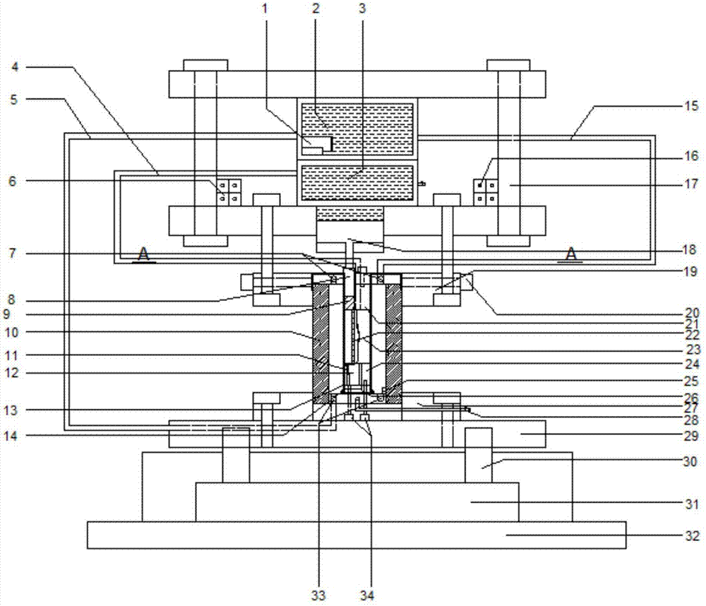
[0003] In order to overcome the deficiency that the prior art cannot consider the effect of shearing in the coupled environment and apply it to CT scanning, the present invention provides a seepage and shearing coupled rock triaxial test system for CT real-time three-dimensional scanning, which effectively solves the problem of rock testing. Confining pressure and seepage of the test piece, and realize the three-dimensional scanning image inside the test piece through the CT device during the seepage and shear test

Method used


Image

  • CT (computer tomography) real-time three-dimensional scanning seepage and shear coupling rock triaxial test system
  • CT (computer tomography) real-time three-dimensional scanning seepage and shear coupling rock triaxial test system
  • CT (computer tomography) real-time three-dimensional scanning seepage and shear coupling rock triaxial test system

Examples


Embodiment Construction

[0020] The present invention will be further described below in conjunction with the accompanying drawings.

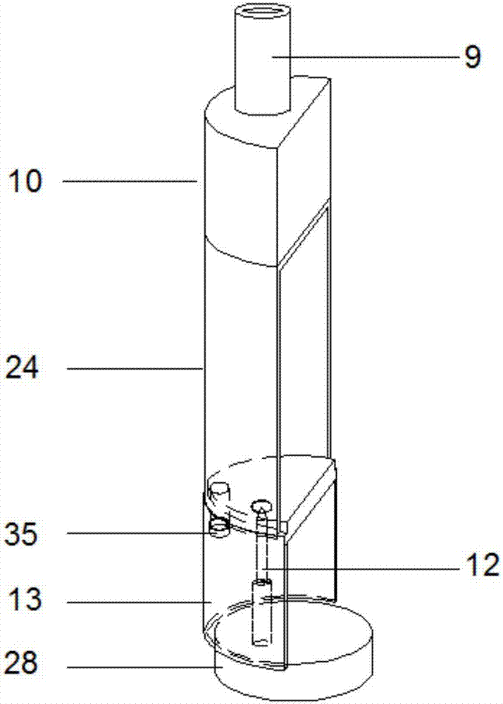
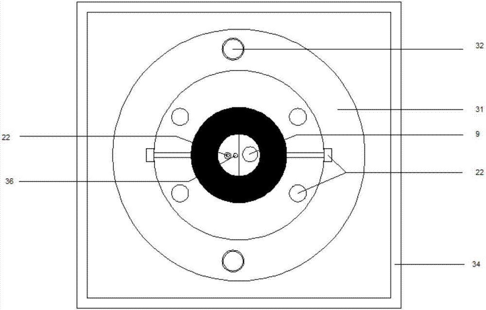
[0021] refer to Figure 1 to Figure 3 , a CT real-time three-dimensional scanning seepage, shear coupled rock triaxial test system, including a main frame with a stable overall structure, a test chamber for shear and seepage tests, a shear loading device controlled by oil pressure, a control The confining pressure servo control system of the test piece, the rotating device driven by the rotating rod to rotate the lower flange rotating base, and the CT scanning device used to obtain the three-dimensional image inside the test piece.

[0022] The main frame includes a base 32 and a reaction frame 17 . Loading device 18, servo control system 6 and 16, water tank 3 and oil tank 2 are placed on the reaction force frame 17; On the rotating device fixed with the base 32, the test room can be irradiated by CT in 360°.

[0023] The test chamber includes a confining pressure ...


PUM


Abstract

The invention discloses a CT (computer tomography) real-time three-dimensional scanning seepage and shear coupling rock triaxial test system which comprises a host frame, a test chamber, a shear loading device, a confining pressure servo control system, a rotary device and a CT scanning device. The host frame is of a stable integral structure, the test chamber is used for carrying out shear and seepage tests, the shear loading device is controlled by oil pressures, the confining pressure servo control system is used for controlling confining pressures of test pieces, a lower flange rotary base of the rotary device can be driven by rotary rods to rotate, and the CT scanning device is used for acquiring three-dimensional images of the insides of the test pieces; the host frame comprises a base and a reaction frame, the rotary device is fixed onto the base, the test chamber is fixed onto the rotary device, the reaction frame is fixed onto the test chamber, and the shear loading device and the servo control system are arranged on the reaction frame; the CT scanning device comprises ray sources and detectors, and the ray sources and the detectors are arranged on two sides of the test chamber. The CT real-time three-dimensional scanning seepage and shear coupling rock triaxial test system has the advantages that the problems of confining pressures and seepage of existing rock test pieces can be effectively solved, and the three-dimensional scanned images of the insides of the test pieces can be acquired by the aid of the CT scanning device in seepage and shear test procedures.

Description

technical field [0001] The invention belongs to the field of geotechnical engineering, and relates to a rock seepage and shear coupling test system, specifically a CT real-time three-dimensional scanning seepage and shear coupling rock triaxial test system. Background technique [0002] In recent years, some complex technical problems about seepage have appeared in many national major geotechnical engineering projects. For example, the damage of dam bedrock will produce pressurized seepage, which will cause concentrated seepage damage to the dam foundation and endanger the overall safety of the dam body; In terms of reservoirs, understanding the seepage law of rock mass is of great significance to solving oil production. This urgently requires geotechnical engineers to build corresponding rock test systems and test methods to accurately evaluate the seepage characteristics of rocks under complex mechanical conditions. Shear failure is a common form of rock mass failure, and...

Claims


Application Information

Patent Timeline
Patent Type & Authority Applications(China)
IPC IPC(8): G01N3/24G01N3/12G01N3/06G01N15/08
CPCG01N3/06G01N3/12G01N3/24G01N15/0826G01N2203/0256G01N2203/0075G01N2203/0048G01N2203/0026G01N2203/0641
Inventor 李博杜时贵周楷峰金栋黄嘉伦雍睿
Owner SHAOXING UNIVERSITY
Learn More