
Method and apparatus to monitor a resolver

A resolver and buffer technology, applied in the field of resolvers

Active Publication Date: 2017-08-11
GM GLOBAL TECH OPERATIONS LLC
View PDF8 Cites 4 Cited by
  • Summary
  • Abstract
  • Description
  • Claims
  • Application Information

AI Technical Summary

Problems solved by technology

The dual-core CPU includes the first CPU and the second CPU

Method used


Image

  • Method and apparatus to monitor a resolver
  • Method and apparatus to monitor a resolver
  • Method and apparatus to monitor a resolver

Examples


Embodiment Construction

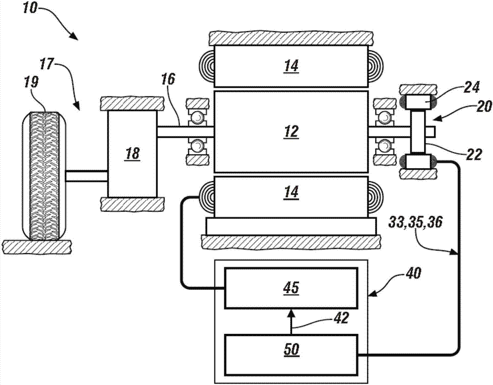
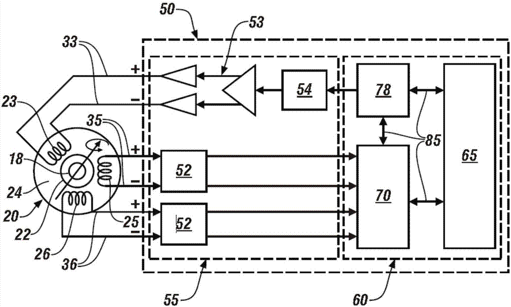
[0014] Referring now to the drawings, wherein the depictions are for purposes of illustrating certain exemplary embodiments only and not for the purpose of limiting such embodiments, figure 1 and figure 2 Schematically showing details of a motor control system for controlling the operation of an electric motor 10 rotatably coupled to a load 17 via a rigid rotatable member 16, wherein the rotational position of the rotatable member 16 is monitored by a resolver 20 , and the operation is controlled by the motor controller 40 . As shown, the resolver 20 is provided on the side of the motor 10 remote from the load 17 , but the resolver 20 may be provided in any suitable location to monitor the rotation of the rotatable member 16 . As a non-limiting example, the load 17 may be a gearbox 18 coupled to drive wheels 19 that cooperate with the ground when used as part of a powertrain system of a land vehicle. The concepts described herein are applicable to any configuration that inc...


PUM


Abstract

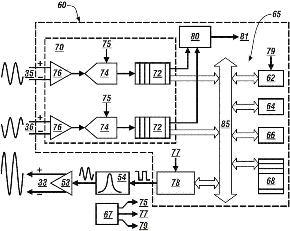
A device for monitoring a resolver disposed on a rotatable member is described herein, and includes a controller including a microprocessor circuit and an interface circuit connected to the resolver, wherein the microprocessor circuit includes a dual-core central processing unit (CPU), a pulse generator, a sigma-delta analog-to-digital converter (SDADC), a global memory device, an internal communication bus and a direct memory access device (DMA). The microprocessor circuit is disposed to control the pulse generator to generate an excitation pulse transferable to the excitation winding of the resolver, and control the SDADC to capture data from the secondary windings of the resolver and store the captured data in the memory buffer. A control routine is executed to detect an envelope for the captured data, and a rotor position for the resolver is determined based upon the detected envelope.

Description

technical field [0001] The present disclosure relates to resolvers, and methods and systems for determining rotational positions associated therewith. Background technique [0002] A device that includes a rotatable member may employ a resolver to monitor the angular position and rotational speed of the rotor. As a non-limiting example, a powertrain system may employ an electric torque machine to generate tractive torque for propulsion. Known torque machines include a polyphase motor / generator that is electrically coupled to an energy storage device via a high voltage electrical bus and inverter modules. Torque machines can use resolvers to monitor rotational position and rotational speed and use this information for their control and operation. [0003] A resolver is an electromechanical converter comprising a rotor having an excitation winding coupled to a rotatable member and a stator having a secondary winding coupled to a non-rotating member of the device, wherein the...

Claims


Application Information

Patent Timeline
IPC IPC(8): H02P23/14H02K11/21
CPCH02P23/14G01P3/488G01D5/2073G01B7/30G06F13/102G06F13/28G06F13/4068G01P3/44G06F3/061G06F3/0656G06F3/0673
Inventor Y·C·孙R·L·霍内尔M·A·范德拉
Owner GM GLOBAL TECH OPERATIONS LLC
Learn More