Circuit board structure and manufacturing method thereof

A manufacturing method and circuit board technology, which are applied in the directions of printed circuit manufacturing, laminated printed circuit boards, circuit covers, etc., to achieve the effect of omitting the pasting steps, reducing production costs, and avoiding cutting waste

Active Publication Date: 2017-08-11
ICHIA TECH
View PDF13 Cites 0 Cited by
  • Summary
  • Abstract
  • Description
  • Claims
  • Application Information

AI Technical Summary

Problems solved by technology

[0004] In more detail, from a microscopic point of view (eg image 3 As shown), based on the board surface 12' of the circuit board 1' has a certain roughness, so the double-sided film 2' is pasted on the circuit board 1', between the double-sided film 2' and the board surface 12' of the circuit board 1' There will still be a gap G, and there may be a gap between the double-sided film 2' and the conductive circuit 11', so there is still room for improvement in the pasting effect of the double-sided film 2'

Method used


Image

  • Circuit board structure and manufacturing method thereof
  • Circuit board structure and manufacturing method thereof
  • Circuit board structure and manufacturing method thereof

Examples


no. 1 example

[0056] see Figure 4 to Figure 8 , which is the first embodiment of the present invention. What needs to be explained first is that this embodiment corresponds to the relevant quantities and shapes mentioned in the accompanying drawings, and is only used to specifically illustrate the implementation of the present invention, so as to facilitate understanding of its content , not to limit the protection scope of the present invention.

[0057] This embodiment is a method for manufacturing a circuit board structure, including step a) to step e). The sequence of steps described below is only for understanding this embodiment, but the sequence of these steps is not limited. The various steps of the manufacturing method of the circuit board structure in this embodiment are roughly described as follows:

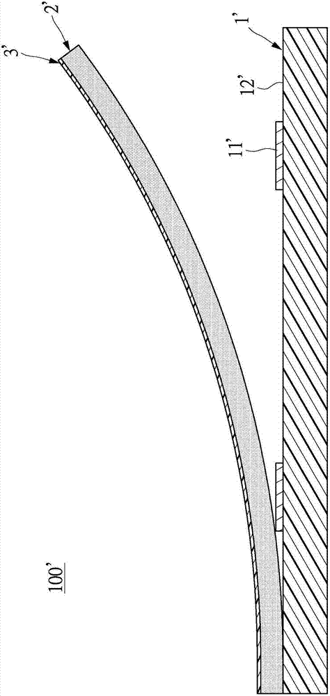
[0058] Step a): See Figure 4 As shown, a circuit board 1 is provided, and the circuit board 1 is preferably a flexible circuit board or a rigid-flex board in this embodiment, bu...

no. 2 example

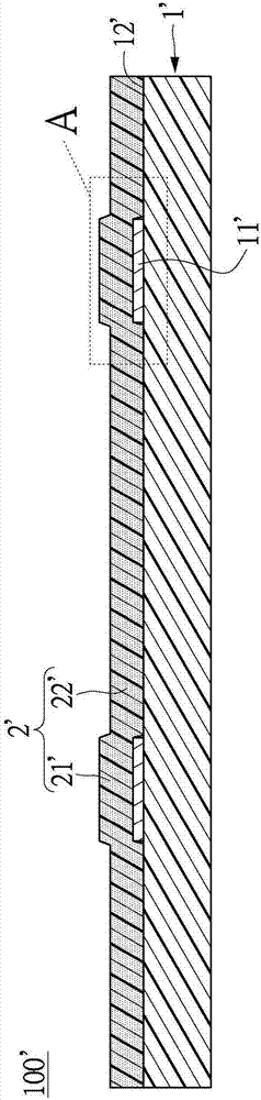
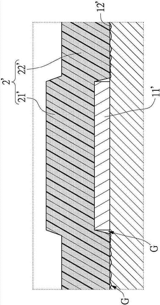
[0076] see Figure 10 to Figure 13 , which is the second embodiment of the present invention. This embodiment is similar to the above-mentioned first embodiment, and the same parts will not be repeated. The difference between the two mainly lies in the manufacturing method of the circuit board structure. The specific differences are as follows:

[0077] Step a): See Figure 10 As shown, a circuit board 1 is provided, and the circuit board 1 is preferably a flexible circuit board or a rigid-flex board in this embodiment, but it is not limited thereto. Wherein, the circuit board 1 has a first board surface 11 and a second board surface 12 on opposite sides, and the circuit board 1 includes at least one conductive circuit 13 arranged on the first board surface 11, the first The board surface 11 defines a predetermined area (not marked), and the conductive circuit 13 is at least partially located on the predetermined area.

[0078] Furthermore, the predetermined area of ​​the fi...


PUM

PropertyMeasurementUnit
thicknessaaaaaaaaaa
thicknessaaaaaaaaaa

Abstract

The invention relates to a circuit board structure and a manufacturing method thereof. The circuit board structure comprises a circuit board and an adhesive layer. The circuit board is provided with a first board surface and a second board surface which are arranged at the opposite sides, and a preset region is defined on the first board surface. The circuit board comprises a conductive line which is arranged on the first board surface, and the conductive line is at least partially arranged on the preset region. The adhesive layer is seamlessly formed on the preset region of the first board surface of the circuit board, and the part of the conductive line arranged on the preset region is seamlessly wrapped by the adhesive layer. The surface, which is away from the circuit board, of the adhesive layer is defined as an adhesive surface, and the adhesive surface is planar. Therefore, the circuit board structure is low in cost and great in adhesive effect.

Description

technical field [0001] The present invention relates to a circuit board, and in particular to a circuit board structure and a manufacturing method thereof. Background technique [0002] see figure 1 and figure 2 As shown, it is a traditional circuit board structure 100', and the above-mentioned traditional circuit board structure 100' is to tear off the double-sided film 2' with release paper on both sides and torn off one of the release paper (Fig. omit), and then attach the double-sided film 2' to the circuit board 1' that has completed the design of the conductive circuit 11', and then tear off another release paper 3' that is adhered to the double-sided film 2' according to the requirements, Therefore, the circuit board 1' is attached to the work surface to be fixed by the double-sided adhesive tape 2'. [0003] However, the circuit board 1' and the double-sided film 2' used in the conventional circuit board structure 100' must be manufactured in two processes, and t...

Claims


Application Information

Patent Timeline
Patent Type & Authority Applications(China)
IPC IPC(8): H05K3/00
CPCH05K3/0058H05K3/0082H05K2201/0738H05K3/28H05K3/4635H05K3/4673C08L83/10C09J183/10H05K3/101H05K1/0298H05K3/22H05K3/4611H05K3/4644H05K2201/0183H05K2203/10
Inventor 孙永祥陈钦
Owner ICHIA TECH
Why Eureka
Try Eureka