Tempered glass production device

A production device and tempered glass technology, applied in glass tempering, glass manufacturing equipment, manufacturing tools, etc., can solve the problems of unqualified glass materials, waste of resources, uneven glass, etc., and achieve good product quality, low production cost, Simple structure of the device

Inactive Publication Date: 2017-08-15
荆门市明豪装饰工程有限公司
View PDF6 Cites 1 Cited by
  • Summary
  • Abstract
  • Description
  • Claims
  • Application Information

AI Technical Summary

Problems solved by technology

[0002] The existing tempered glass production device includes a support, on which a conveying roller, a tempering furnace and a cooling device are arranged. The existing equipment has the following deficiencies: one, because the existing conveying roller is hollow, the conveying roller is under the pressure of the glass itself under the action of gravity. The middle part tends to bend toward the ground, which makes the glass uneven during the tempering process; the second is that the "heat balance system" of the traditional glass tempering furnace uses compressed air in the factory as the air source, and the air is drawn from the outside and sent to the ground. into the furnace body to generate airflow in the furnace body, and the cold wind blowing into the furnace body is mixed with the heat in the furnace body to make the temperature in the furnace body drop, and the temperature in the furnace body fails to reach the preset temperature. When the temperature in the furnace body reaches the preset temperature, the power of the heater in the furnace body should be increased. This method will increase the use cost of the tempering furnace, consume a lot of heat, and cause waste of resources. Moreover, when the cold wind blows to the high-temperature glass material When the high-temperature glass material is bent, deformed, pitted, etc., the glass material is unqualified and must be scrapped as a whole; the third is that the high-pressure air blown to the glass surface of the traditional cooling device needs to be consistent with the ambient temperature, humidity, and atmospheric pressure. , which requires relatively high pressure of the blown high-pressure air, which greatly increases the production cost

Method used


Image

  • Tempered glass production device

Examples


Embodiment Construction

[0012] The technical solution of this patent will be further described in detail below in conjunction with specific embodiments.

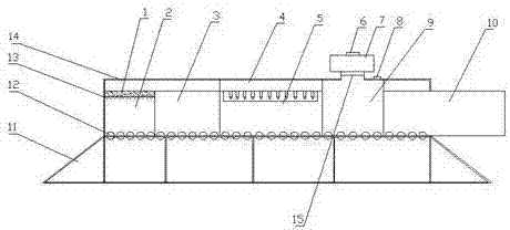
[0013] see figure 1 , a tempered glass production device of the present invention, comprising a support 11 and a tempering furnace 14, the upper end of the support 11 is provided with a tempering furnace 14, and the tempering furnace 14 includes a high temperature zone 2, a heat preservation zone 3, a forming zone 5, and a cooling zone 9 and the storage area 10, the high temperature area 2, the heat preservation area 3 and the upper end of the forming area 5 are provided with a constant temperature area 4, and a conveying roller 12 is provided between the support 11 and the tempering furnace 14, and the heat preservation area 3 is located in the high temperature area 2 Between the high temperature zone 2 and the forming zone 5, a heater 1 is provided at the upper end of the interior of the high temperature zone 2, a heating wire 13 is provided at t...


PUM


Abstract

The invention belongs to the technical field of high-temperature treatment and discloses a tempered glass production device. The device comprises a bracket and a tempering furnace, wherein the tempering furnace is arranged at the upper end of the bracket and comprises a high-temperature area, a thermal insulation area, a molding area, a cooling area and a storage area; a conveying roller is arranged between the bracket and the tempering furnace; the thermal insulation area is positioned between the high-temperature area and the molding area; a heater is arranged at the upper end inside the high-temperature area; a heating wire is arranged at the lower end of the heater; the molding area is formed at one side of the cooling area; and the storage area is formed at the other side of the cooling area. According to the movement of tempered materials on the conveying roller, by virtue of a series of actions of the high-temperature area, the thermal insulation area, the molding area, the cooling area and the storage area, the tempered glass is finally formed. The device disclosed by the invention is simple in structure, low in production cost and good in product quality, can easily meet the requirements of people and can be popularized in the market on a large scale.

Description

technical field [0001] The invention relates to the technical field of high-temperature manufacturing, in particular to a tempered glass production device. Background technique [0002] The existing tempered glass production device includes a support, on which a conveying roller, a tempering furnace and a cooling device are arranged. The existing equipment has the following deficiencies: one, because the existing conveying roller is hollow, the conveying roller is under the pressure of the glass itself under the action of gravity. The middle part tends to bend toward the ground, which makes the glass uneven during the tempering process; the second is that the "heat balance system" of the traditional glass tempering furnace uses compressed air in the factory as the air source, and the air is drawn from the outside and sent to the ground. into the furnace body to generate airflow in the furnace body, and the cold wind blowing into the furnace body is mixed with the heat in the...

Claims


Application Information

Patent Timeline
Patent Type & Authority Applications(China)
IPC IPC(8): C03B27/012
CPCC03B27/012
Inventor 卢香君
Owner 荆门市明豪装饰工程有限公司
Why Eureka
Try Eureka