Transfer case and crane
A transfer case and crane technology, applied in the direction of mechanical equipment, traveling mechanism, transmission device, etc., can solve the problems of low reliability, high manufacturing cost, complicated control process, etc., and achieve convenient operation, simple structure, and simple operating system Effect
- Summary
- Abstract
- Description
- Claims
- Application Information
AI Technical Summary
Problems solved by technology
Method used
Image
Examples
Embodiment 1
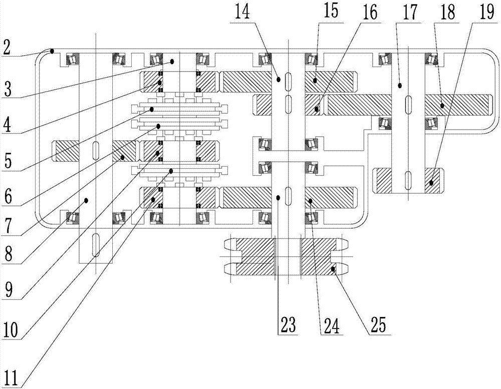
[0039] Embodiment 1 of the present invention provides a transfer case, see figure 1 , the transfer case includes a case body 2, a transfer shaft 3, a transmission member, a shifting device and at least three output shafts.
[0040] Wherein, the transfer shaft 3 is used as the power output and output shaft of the transfer case, and the transfer shaft 3 is arranged in the case body 2, specifically, the transfer shaft 3 is arranged in the case body 2 through a bearing.
[0041] In this embodiment, the output shaft is also arranged in the box body 2, specifically, it can be arranged in the box body 2 through a bearing or a bearing and a bearing seat, and the number of output shafts is at least three, preferably three.
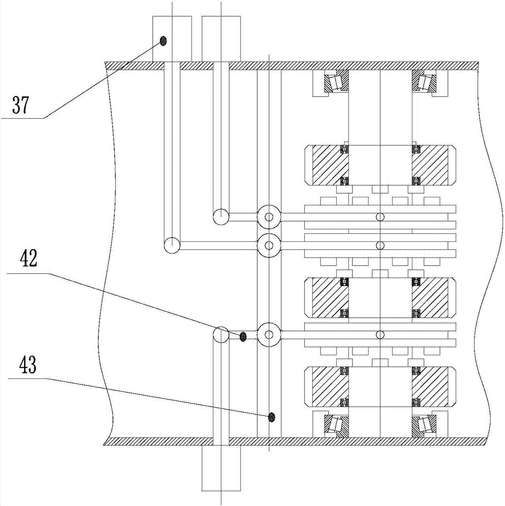
[0042] The transmission part is arranged on the transfer shaft 3, and the transmission part is used to drive the output shaft to rotate, and the transmission part can idle relative to the transfer shaft 3, and the transmission part can still be arranged on the tran...
Embodiment 2
[0070] Embodiment 2 of the present invention provides a crane, refer to Figure 7 with Figure 8 , the crane includes a motor 1, a reducer 13 and a first transmission mechanism for driving the crane to move, a slewing bearing 21 for driving the crane to rotate, a second transmission mechanism for lifting the crane, a vehicle frame, an elevator 34, and a balance beam 20 and the aforementioned transfer case.
[0071] Wherein, the output shaft of the motor 1 is in transmission connection with the transfer shaft 3 of the transfer case, and the motor 1 provides power to drive the transfer shaft 3 to rotate.
[0072] Vehicle frame comprises driving vehicle frame 30 and driven vehicle frame 35, and each crane comprises driving vehicle frame 30 and driven vehicle frame 35, and driving vehicle frame 30 and driven vehicle frame 35 are all connected with balance beam 20 by slewing bearing 21, and elevator 34 Then it is connected with the middle part of the balance beam 20 , and a tie r...
PUM
 Abstract
Description
Claims
Application Information
 - R&D
- Intellectual Property
- Life Sciences
- Materials
- Tech Scout
- Unparalleled Data Quality
- Higher Quality Content
- 60% Fewer Hallucinations
Browse by: Latest US Patents, China's latest patents, Technical Efficacy Thesaurus, Application Domain, Technology Topic, Popular Technical Reports.
© 2025 PatSnap. All rights reserved.Legal|Privacy policy|Modern Slavery Act Transparency Statement|Sitemap|About US| Contact US: help@patsnap.com


