Vehicular unmanned aerial vehicle mooring communication reconnaissance system

A communication system and unmanned rotor technology, applied in the field of drones, can solve problems such as failure to work normally, low load capacity, and limited transmission distance, etc., to expand communication coverage, solve transmission bandwidth problems, and realize backhaul Effect

Inactive Publication Date: 2017-08-15
BEIJING INST OF COMP TECH & APPL
View PDF4 Cites 26 Cited by
  • Summary
  • Abstract
  • Description
  • Claims
  • Application Information

AI Technical Summary

Problems solved by technology

[0003] Satellite communication equipment has the advantages of not relying on public infrastructure and long transmission distance, but the disadvantages are high cost of use and low transmission bandwidth; microwave communication equipment has the advantages of high transmission bandwidth and strong adaptability, but the disadvantage is that The transmission distance is limited; the 3G / 4G mobile communication network makes full use of the current infrastructure, which has the advantages of low cost of use and wide coverage, but it depends on the on-site infrastructure and is susceptible to base station working conditions, the number of working sector terminals, and signal interference Devices and other influences
[0004] The rechargeable rotor UAV can collect video data well in the air, but the load capacity is not more than 5Kg, and the suspension time is only 2 hours at most, and it is greatly affected by the environment and cannot work normally under strong wind conditions; fixed wing There are two forms of charging and fuel for UAVs, but fixed-wing UAVs need to move continuously in a certain area, and cannot continuously and effectively obtain video data of a key point, and cannot be used as a relay carrier platform to hover in one place , while its air time is as limited as that of a rechargeable rotorcraft

Method used


Image

  • Vehicular unmanned aerial vehicle mooring communication reconnaissance system
  • Vehicular unmanned aerial vehicle mooring communication reconnaissance system
  • Vehicular unmanned aerial vehicle mooring communication reconnaissance system

Examples


Embodiment Construction

[0025] In order to make the purpose, content, and advantages of the present invention clearer, the specific implementation manners of the present invention will be further described in detail below in conjunction with the accompanying drawings and embodiments.

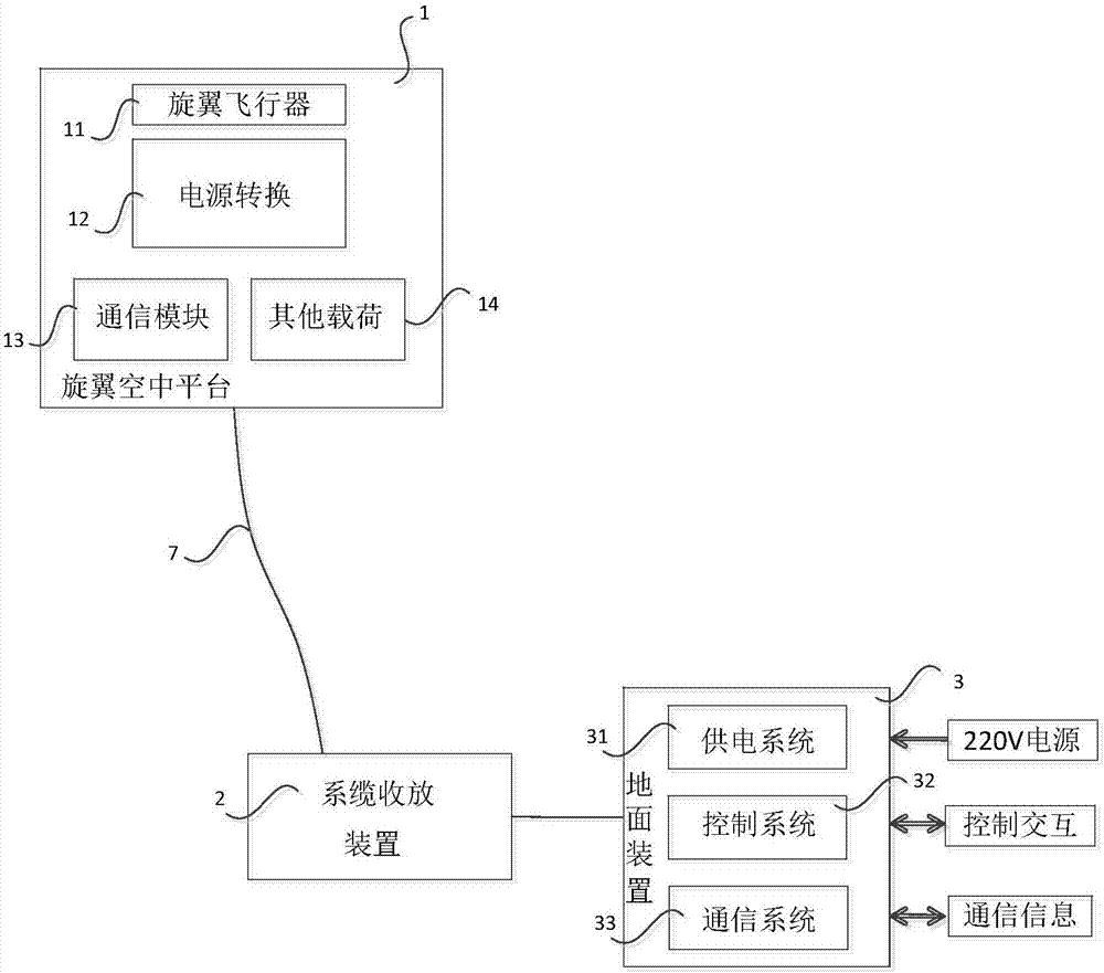
[0026] figure 1 Shown is a schematic diagram of the vehicle-mounted UAV tethered communication reconnaissance system, such as figure 1 As shown, the tethered power supply and communication system of the rotor unmanned aerial vehicle adopts the tethered power supply mode to realize the continuous flight of the rotor unmanned aerial vehicle. Composite mooring cable 7, mooring cable take-up and release device 2, ground device 3. The ground device 3 includes a ground power supply system 31 , a control system 32 and a communication system 33 . The rotor aerial platform 1 includes a wing aircraft 11 , a power conversion module 12 , a communication module 13 and other loads 14 .

[0027] Such as figure 1 As shown, the rot...


PUM


Abstract

The invention discloses a rotor unmanned aerial vehicle mooring power supply and communication system. The system comprises a power supply conversion module which is used for converting a high-voltage direct current of a ground power supply system into a low-voltage direct current required by a rotor aerial vehicle, a communication module and other loads; a photoelectric composite mooring line which is used for transmitting power and transmitting information; a mooring line deploying and retracting device which is used for adjusting a deploying length of the photoelectric composite mooring line in real time according to a height of the aerial vehicle; the ground power supply system which is used for converting ground power into A power form applicable to transmission of the photoelectric composite mooring line and supplying the power to the aerial vehicle and task loads; a control system which is used for monitoring a posture of the rotor unmanned aerial vehicle; a communication system which is used for supplying a communication interface between the task loads carried by the rotor unmanned aerial vehicle and a ground device; and a communication module which is used for communicating with the communication system and is used as a communication relay of the ground device for sending wireless information.

Description

technical field [0001] The invention relates to the technical field of unmanned aerial vehicles, in particular to a vehicle-mounted unmanned aerial vehicle tethered communication reconnaissance system. Background technique [0002] In cities, towns and their surrounding areas, when natural disasters, large-scale group activities or violent terrorist incidents occur, the 3G / 4G mobile communication network that relies on basic communication facilities is likely to face paralysis. However, when the above-mentioned incidents occur, the relevant personnel often need to pass the situation of the incident area to the rear personnel, so that the rear personnel can correctly handle or make decisions. At the same time, an effective video data collection platform is needed, which can monitor the situation in a certain area for a long time. The situation is collected, processed and sent back. At this time, how to obtain video data uninterruptedly for a long time and transmit it through...

Claims


Application Information

Patent Timeline
Patent Type & Authority Applications(China)
IPC IPC(8): H04B7/185H04B10/2575H04B10/40H04W88/06H02J5/00
Inventor 李鹏闫国玉马承振刘锟戈建伟
Owner BEIJING INST OF COMP TECH & APPL
Why Eureka
Try Eureka