
Baking ray capable of being heated from bottom, and light wave electric oven using same

A bottom heating, baking pan technology, applied in special baking containers, applications, roasters/barbecue grids, etc., can solve the problems of difficult heating pipes, affecting the heat preservation of food in the baking pan, slow heat conduction heating efficiency, etc. effect of speed

Active Publication Date: 2017-08-18
罗江祺
View PDF5 Cites 1 Cited by
  • Summary
  • Abstract
  • Description
  • Claims
  • Application Information

AI Technical Summary

Problems solved by technology

[0002] Light-wave electric ovens, especially open-type light-wave electric ovens, users can operate electric ovens while roasting food. Due to the convenience of consumers, they are more and more popular among consumers. The light-wave electric ovens in the prior art , including the base, the baking pan installed on the base, and the light wave heat source above the baking pan. The food on the baking pan is radiated by the heat source on the top. Since the heat source on the top heats the food on the baking pan in the form of heat radiation For baking, the heating efficiency is relatively slow compared to heat conduction, and only one side of the food can be heated, the heating speed of the food is slow, and the user also needs to turn the food frequently to make the food more evenly heated; When the heat source of the oven is turned off, due to the use of radiant heating and open structure, the cooling speed of the baking pan is faster, which affects the heat preservation of the food on the baking pan
[0003] However, the baking pan of the light-wave electric oven in the prior art, because the whole electric oven is set in an open type, the user may need to rotate the baking pan to facilitate the baking of food by himself when the electric oven is practical, and the rotation of the baking pan makes the grilling It is quite difficult to install the heat pipe at the bottom of the pan

Method used


Image

  • Baking ray capable of being heated from bottom, and light wave electric oven using same
  • Baking ray capable of being heated from bottom, and light wave electric oven using same
  • Baking ray capable of being heated from bottom, and light wave electric oven using same

Examples


Embodiment Construction

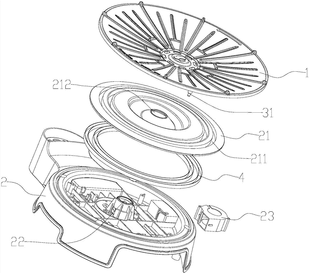
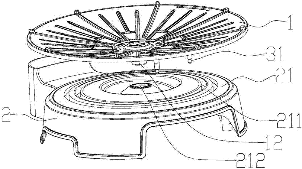
[0022] A bottom heating pan and a light-wave electric oven using the pan are described in conjunction with the accompanying drawings.

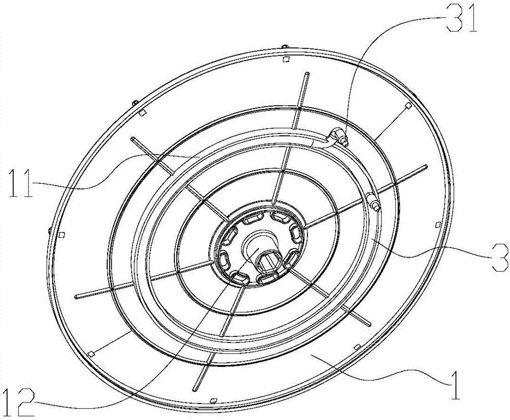
[0023] A bottom heating baking pan and a light-wave electric oven using the baking pan, such as Figures 1 to 4 As shown, it includes a baking pan 1, a base 2 for installing the baking pan 1, and a light-wave heat source 5. The light-wave heat source 5 is fixed on the base 2 through a support structure 6 and is set overhead on the top of the baking pan 1. The baking pan 1 can be It is installed in rotation on the base 2; it also includes a heating tube 3, the heating tube 3 is arranged on the bottom surface of the baking pan 1, and an electrode 31 extends to the base 2 of the baking pan 1, and the base 2 is provided with a power supply structure, The power supply structure connects the electrodes 31 to supply power to the heating tube 3 .

[0024] further, Figures 2 to 3 As shown, the bottom surface of the baking pan 1 is provided with a ro...


PUM


Abstract

The invention discloses a baking ray capable of being heated from the bottom, and a light wave electric oven using the same. The baking tray comprises a baking tray body and a pedestal for mounting the baking tray body, and the baking tray body is rotatably arranged on the pedestal; the baking tray also comprises a first heat source; the first heat source is arranged on the bottom surface of the baking tray body and extends toward the pedestal of the baking tray body to form an electrode; a power supply structure is arranged on the pedestal; and the power supply structure is connected with the electrode to supply power to the first heat source. The heating device is arranged at the bottom of the baking tray and can heat food on the baking tray from the bottom, and the waste heat of the heating device can perform heat preservation on the food on the baking tray when heating is stopped.

Description

technical field [0001] The invention relates to the field of kitchen electrical components, in particular to a bottom heating baking pan and a light-wave electric oven using the baking pan. Background technique [0002] Light-wave electric ovens, especially open-type light-wave electric ovens, users can operate electric ovens while roasting food. Due to the convenience of consumers, they are more and more popular among consumers. The light-wave electric ovens in the prior art , including the base, the baking pan installed on the base, and the light wave heat source above the baking pan. The food on the baking pan is radiated by the heat source on the top. Since the heat source on the top heats the food on the baking pan in the form of heat radiation For baking, the heating efficiency is relatively slow compared to heat conduction, and only one side of the food can be heated, the heating speed of the food is slow, and the user also needs to turn the food frequently to make th...

Claims


Application Information

Patent Timeline
IPC IPC(8): A47J37/06A47J37/01
CPCA47J37/015A47J37/0629
Inventor 罗江祺
Owner 罗江祺
Learn More