
Mechanical arm and medical instrument

A technology of a mechanical arm and an energy storage device, applied in the field of equipment, can solve problems such as poor operability, and achieve the effects of easy maintenance, good operability, flexible rotation and locking

Pending Publication Date: 2017-08-18
重庆金创谷医疗科技有限公司
View PDF0 Cites 4 Cited by
  • Summary
  • Abstract
  • Description
  • Claims
  • Application Information

AI Technical Summary

Problems solved by technology

[0004] The purpose of the present invention is to provide a mechanical arm and a medical device, which aims to improve the existing problem of poor operability

Method used


Image

  • Mechanical arm and medical instrument
  • Mechanical arm and medical instrument
  • Mechanical arm and medical instrument

Examples


Embodiment

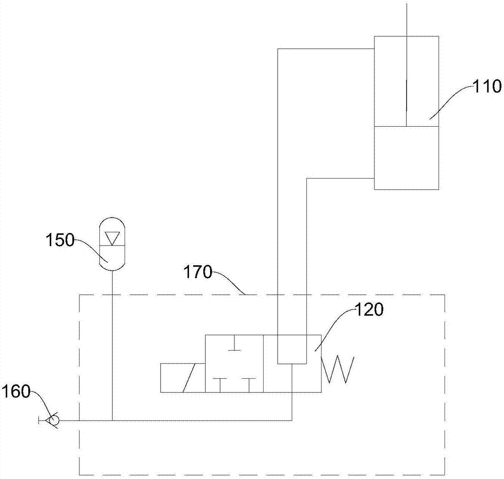
[0034] figure 1 A schematic structural diagram of the robotic arm 100 provided by the embodiment of the present invention. see figure 1 , this embodiment provides a mechanical arm 100 , the mechanical arm 100 includes a hydraulic cylinder 110 , a control valve 120 , a first arm 130 , a second arm 140 , and an accumulator 150 . The control valve 120 is respectively connected to the inlet and outlet 111 of the rod chamber and the inlet and outlet 113 of the rodless chamber of the hydraulic cylinder 110 , and the accumulator 150 is connected to the hydraulic cylinder 110 through the control valve 120 . Both ends of the hydraulic cylinder 110 are rotatably connected to the first arm 130 and the second arm 140 respectively, and the hydraulic cylinder 110 can drive the second arm 140 to rotate relative to the first arm 130 .

[0035] Further, when the control valve 120 is a two-position three-way solenoid valve, the control valve 120 has a first inlet and outlet, a second inlet an...


PUM


Abstract

The invention relates to the field of instruments, in particular to the field of medical instruments, and is a mechanical arm and a medical instrument. A mechanical arm includes a control valve, a hydraulic cylinder, a first arm, a second arm, and an accumulator. The control valve is respectively connected with the hydraulic cylinder and the accumulator. Two ends of the hydraulic cylinder are respectively connected in rotation with the first arm and the second arm, and the hydraulic cylinder can drive the second arm to rotate relative to the first arm. The oil pressure difference caused by the expansion and contraction of the piston rod of the hydraulic cylinder can be replenished and stored through the accumulator. A medical device includes the above-mentioned mechanical arm. The closing or opening of the hydraulic circuit formed by the hydraulic cylinder is controlled by the control valve, thereby controlling the rotation and locking of the second arm relative to the first arm. The entire hydraulic circuit also includes pressure measuring joints and oil circuit valve blocks. Thus, the flexible rotation and locking of the mechanical arm can be realized, and the operability is good and the maintenance is convenient.

Description

technical field [0001] The invention relates to the field of instruments, in particular to the field of medical instruments, and is a mechanical arm and a medical instrument. Background technique [0002] Most of the existing medical manipulators use purely mechanical structures (bolt locking the rotating shaft, thread pre-tightening the rotating shaft, etc.) to realize the rotation and intermittent locking of the mechanical arm, or use a gas spring to cooperate with an eccentric mechanism to achieve rotation and stepless locking. , or use a motor to achieve rotation and locking. [0003] The medical manipulator with a purely mechanical structure has poor practicability and operability, and the joints of the manipulator cannot be infinitely locked within the rotation range, and if it is applied to rotate around a horizontal axis (or an axis that intersects the horizontal plane at an acute angle within 45°) , itself is affected by gravity and causes trouble in operation. Me...

Claims


Application Information

Patent Timeline
IPC IPC(8): B25J9/14B25J9/08A61B34/30
CPCB25J9/14B25J9/08
Inventor 付铎文豪冯德友
Owner 重庆金创谷医疗科技有限公司
Learn More