Shape follow-up mold and method for additionally installing composite abrasion-resistant layer on metal component

A metal component and wear-resistant layer technology, applied in the field of conformal molds, can solve the problems of difficult forming, low yield and high processing cost, improve the ability to resist the impact of large particles, reduce the probability of dark cracks, and simplify installation. The effect of the process

Pending Publication Date: 2017-08-18
新疆鼎新特种材料有限公司
View PDF14 Cites 0 Cited by
  • Summary
  • Abstract
  • Description
  • Claims
  • Application Information

AI Technical Summary

Problems solved by technology

[0012] The purpose of the present invention is to provide a conformal mold and method for installing a composite wear-resistant layer on metal components, which solves the need to make separate molds for the wear-resistant layers of different equipment, high processing costs, difficult molding, and low yield technical issues

Method used


Image

  • Shape follow-up mold and method for additionally installing composite abrasion-resistant layer on metal component
  • Shape follow-up mold and method for additionally installing composite abrasion-resistant layer on metal component

Examples


Embodiment 1

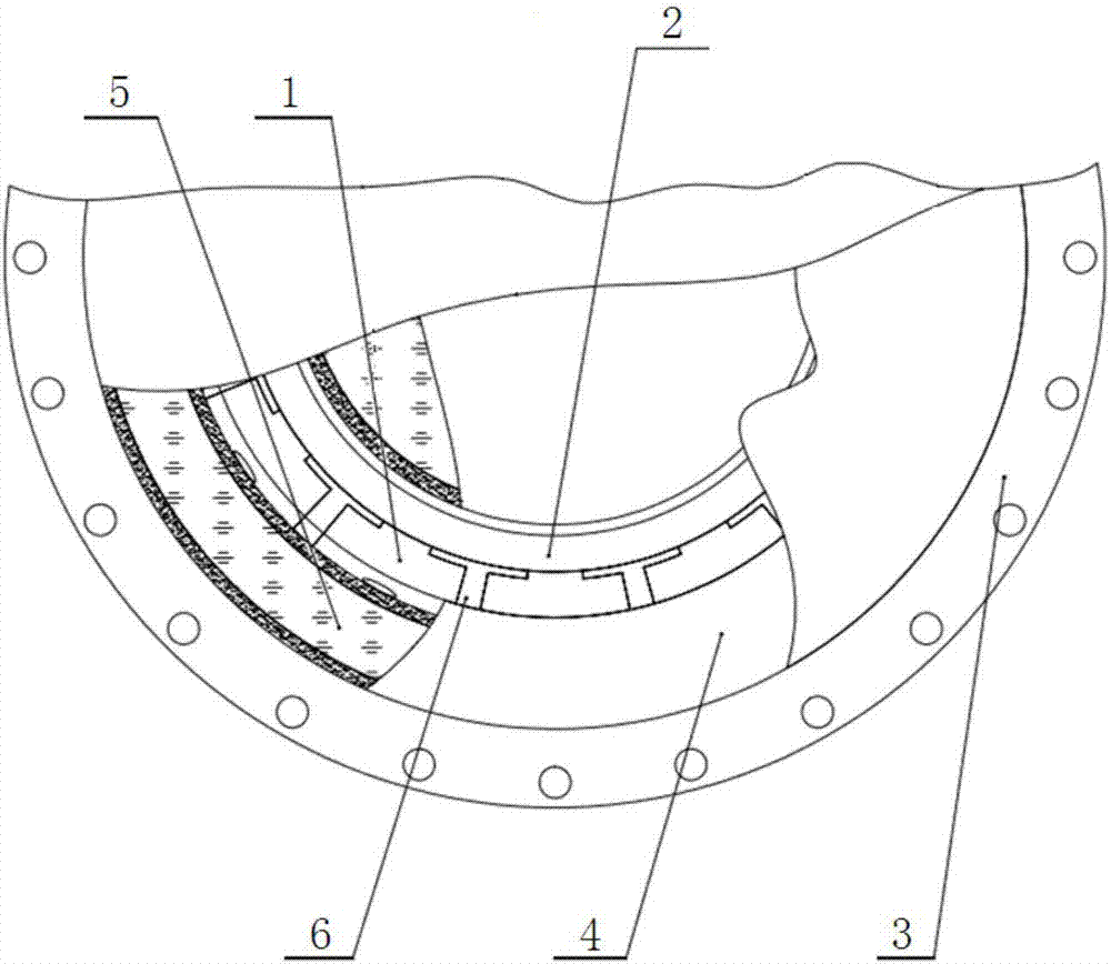
[0042] This embodiment is a method for installing a composite abrasion-resistant layer on a grinding roller, the method comprising the following steps:

[0043] 1) The prefabricated wear-resistant block 1 is made of structural ceramics; the structural ceramics can be composed of one or more of alumina ceramics, silicon carbide ceramics, and silicon nitride ceramics.

[0044] 2) fixing a plurality of prefabricated wear-resistant blocks 1 on the wear-resistant layer mounting surface of the grinding roller 2 through bolts;

[0045]3) Place the grinding roller 2 fixed with the prefabricated wear-resistant block 1 in the rigid forming cavity 3, and place it between the prefabricated wear-resistant block 1 and the rigid forming cavity 3 and between the grinding roller 2 and the rigid forming cavity 3 A plurality of flexible mold bags 4 made of rubber;

[0046] 4) Inject liquid fluid 5 into the flexible mold bag 4 through the liquid injection channel and discharge air, so that the f...

Embodiment 2

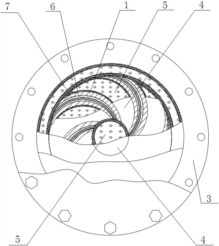
[0055] This embodiment is a method for installing a composite abrasion-resistant layer on the impeller of the pump body. The method includes the following steps:

[0056] 1) Prefabricated wear-resistant block 1 is made of a composite material of wear-resistant particles and thermosetting resin;

[0057] 2) Using an adhesive to fix a plurality of prefabricated wear-resistant blocks 1 on the wear-resistant layer mounting surface of the impeller 7;

[0058] 3) Place the impeller 7 fixed with the prefabricated wear-resistant block 1 in the rigid forming cavity 3, and place one or A plurality of flexible mold bags 4 made of elastic plastic material;

[0059] 4) Inject liquid fluid 5 into the flexible mold bag 4 through the liquid injection channel and discharge air, so that the flexible mold bag 4 fills the space between the prefabricated wear-resistant block 1 and the rigid molding cavity 3;

[0060] 5) Inject the wear-resistant filler 6 into the rigid molding cavity 3 through t...


PUM

PropertyMeasurementUnit
particle diameteraaaaaaaaaa

Abstract

The invention belongs to the technical field of materials, and particularly relates to a shape follow-up mold and a method for additionally installing a composite abrasion-resistant layer on a metal component. The shape follow-up mold comprises a rigid molding cavity, one or more flexible mold bags and a plurality of prefabricated abrasion-resistant blocks, wherein the prefabricated abrasion-resistant blocks are fixed on the installing surface of the abrasion-resistant layer of the metal component, the flexible mold bags are used for filling the space between the rigid molding cavity and the prefabricated abrasion-resistant blocks and the space between the rigid molding cavity and the metal component; and an abrasion-resistant filling material injection channel is formed in the rigid molding cavity, and liquid injection channels are formed in the flexible mold bags. The installation of the abrasion-resistant layers with various complex structures can be completed only be using one set of shape follow-up mold, and matched molds do not need to be produced and manufactured independently, so that the installation process of the abrasion-resistant layer is simplified while the installation cost of the abrasion-resistant layer is reduced, and the installation efficiency of the abrasion-resistant layer is improved.

Description

technical field [0001] The invention belongs to the technical field of materials, and in particular relates to a conformal mold and a method for installing a composite wear-resistant layer on a metal component. Background technique [0002] Abrasion is a relatively special type of corrosion failure formed by the simultaneous action of wear and corrosion or cavitation. Correspondingly, abrasion resistance is a very important one of many indicators to measure the performance of materials, especially for structural components used in environments with high-speed flowing solid particles or corrosive fluids, its wear resistance The quality of corrosion performance is related to the safety, stability and service life of the entire equipment. [0003] In order to reduce the impact of material abrasion on equipment operation, the most direct method is to use structural ceramics (such as silicon carbide ceramics) or composite materials with good abrasion resistance (such as composit...

Claims


Application Information

Patent Timeline
Patent Type & Authority Applications(China)
IPC IPC(8): B29C43/12B29C43/18B29C43/36
CPCB29C43/12B29C43/18B29C43/3642B29C2043/189B29C2043/3644
Inventor 朱胜利
Owner 新疆鼎新特种材料有限公司
Why Eureka
Try Eureka