Plunger pump-based transport robot

A robot and plunger pump technology, applied in the field of robotics, can solve problems such as large impact on the road surface, unstable robot movement, and untimely turning of the robot

Active Publication Date: 2017-08-18
DEEPBLUE ROBOTICS (SHANGHAI) CO LTD
View PDF5 Cites 6 Cited by
  • Summary
  • Abstract
  • Description
  • Claims
  • Application Information

AI Technical Summary

Problems solved by technology

[0003] The currently used transportation robots have complex structures and are mostly directly driven by motors. Such transportation robots are subjected to a large impact on the road during their work, and affected by the motor, it is common for the robot to be unstable during its movement. Separa

Method used


Image

  • Plunger pump-based transport robot
  • Plunger pump-based transport robot
  • Plunger pump-based transport robot

Examples


Embodiment Construction

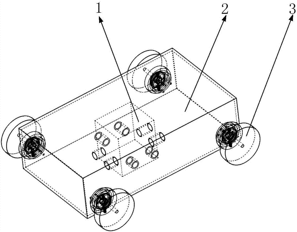
[0030] Such as figure 1 As shown, it includes a driving device 1, a vehicle body 2, and a driving wheel unit 3, wherein the driving device 1 is installed on the bottom surface of the vehicle body 2; And the two driving wheel units 3 on the same side are located at both ends of the vehicle body 2 .

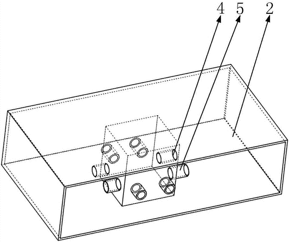
[0031] Such as figure 1 , 2 As shown, the above-mentioned drive device 1 includes a motor, a first hydraulic port 4, a second hydraulic port 5, an oil pump, a control chip, and an oil tank, wherein one first hydraulic port 4 and one second hydraulic port 5 form a group, and the four groups are all Installed on the outer wall of the driving device 1, and all cooperate with the oil pump and the oil tank.

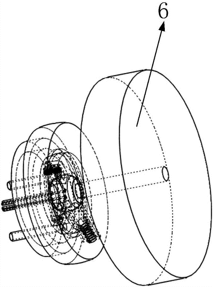
[0032] Such as image 3 As shown, the above-mentioned drive wheel unit 3 includes a spherical cavity 42, a wheel 6, a third hydraulic pipe 7, a fourth hydraulic pipe 8, a fifth hydraulic pipe 9, a seventh oil passage 50, an eighth oil passage 51, and a ninth oil passage. 52. T...


PUM


Abstract

The present invention belongs to the technical field of robots, and especially relates to a plunger pump-based transport robot. The robot comprises a drive device, a body and drive wheel units, wherein the drive device is mounted on the bottom surface of the interior of the body; the four drive wheel units are symmetrically mounted on the both sides of the body in pairs, and the two drive wheel units on the same side are positioned on the two ends of the body; and the drive device comprises a motor, a first hydraulic port, a second hydraulic port, an oil pump, a control chip and an oil tank. When the robot straightly runs, all the four drive wheel units move, when the transport robot needs to turn a corner or reverse, only two drive wheel units move, and thus the function of quick cornering or reversing is fulfilled; and the drive device has a function of supplying power for the four drive wheel units. According to the invention, the rotation centerlines of wheels of the drive wheel units are coincided with the axis of a housing, when the wheels make a turn, the wheels rotate around the axis of the housing as a whole if being driven, and thus the drive wheel units which make a turn are not driven.

Description

[0001] Technical field [0002] The invention belongs to the technical field of robots, in particular to a transport robot based on a plunger pump. Background technique [0003] The currently used transportation robots have complex structures and are mostly directly driven by motors. Such transportation robots are subjected to a large impact on the road during their work, and affected by the motor, it is common for the robot to be unstable during its movement. Separate control from turning, the turning of the robot is not timely, so a transport robot that is controlled by a control device for straight-line driving and turning is needed. At the same time, the robot moves smoothly and has the function of shock absorption. [0004] The present invention designs a transport robot based on a plunger pump to solve the above problems. Contents of the invention [0005] In order to solve the above-mentioned defects in the prior art, the present invention discloses a transport robot...

Claims


Application Information

Patent Timeline
IPC IPC(8): B60K17/10B60G11/14
CPCB60G11/14B60K17/10
Inventor 战星罡
Owner DEEPBLUE ROBOTICS (SHANGHAI) CO LTD
Why Eureka
Try Eureka