
Platinum channel flow control system

A platinum channel and flow control technology, used in manufacturing tools, glass manufacturing equipment, glass furnace equipment, etc., can solve the problems of multi-platinum, increased investment, restricting the length of the platinum channel flow control loop and the number of loops, etc.

Active Publication Date: 2017-08-18
DONGXU OPTOELECTRONICS TECH CO LTD
View PDF3 Cites 9 Cited by
  • Summary
  • Abstract
  • Description
  • Claims
  • Application Information

AI Technical Summary

Problems solved by technology

[0011] The above problems can be solved by increasing the length and number of platinum channel flow control loops, but this will increase the investment in the use of precious metals, electrical equipment, and plant construction, and the increase in the length of the platinum channel will also bring More platinum stone defects
Many production lines are upgraded on the basis of existing plant equipment, and the layout of the existing plant design also restricts the length and number of platinum channel flow control loops

Method used


Image

  • Platinum channel flow control system
  • Platinum channel flow control system
  • Platinum channel flow control system

Examples


Embodiment 1

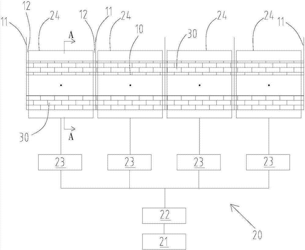
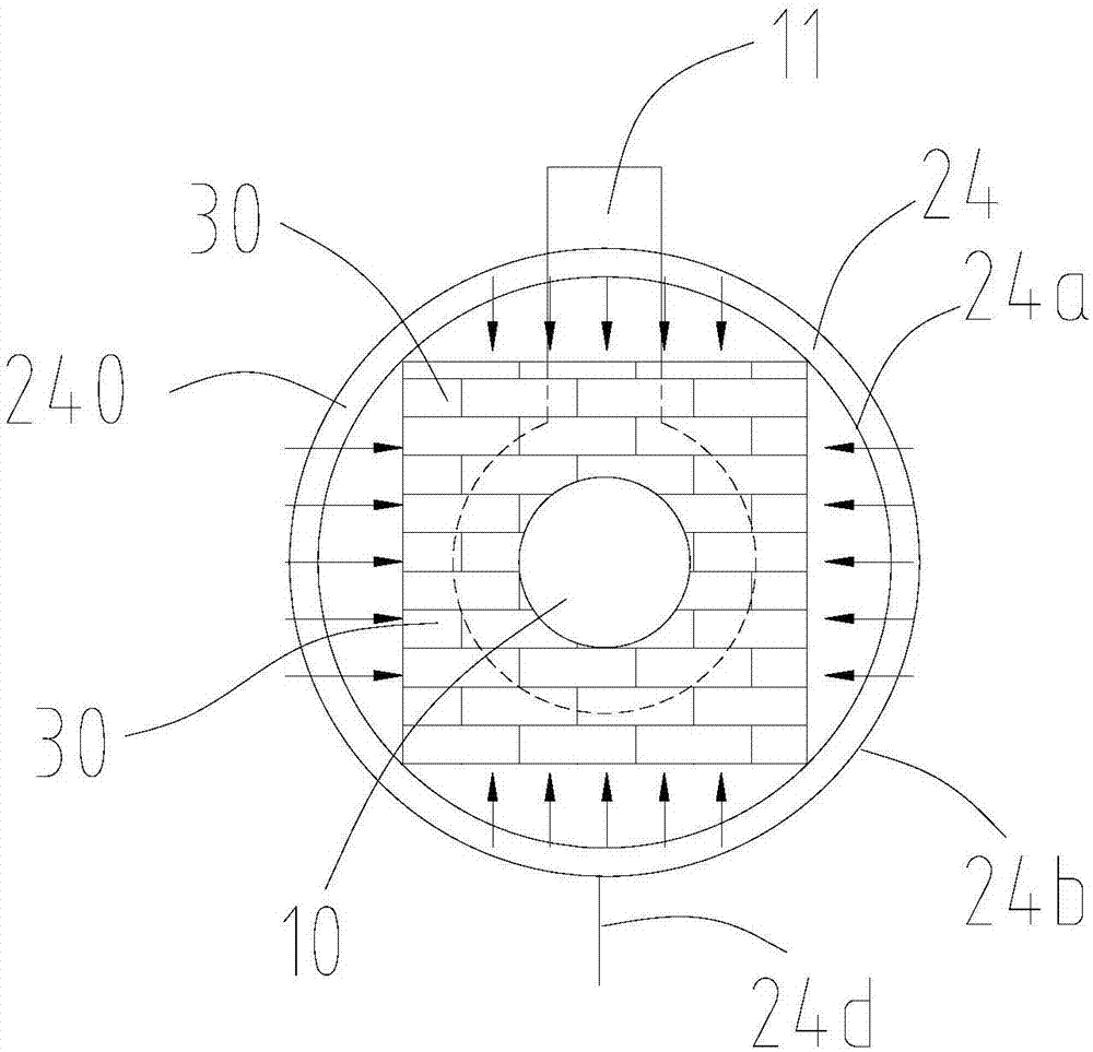
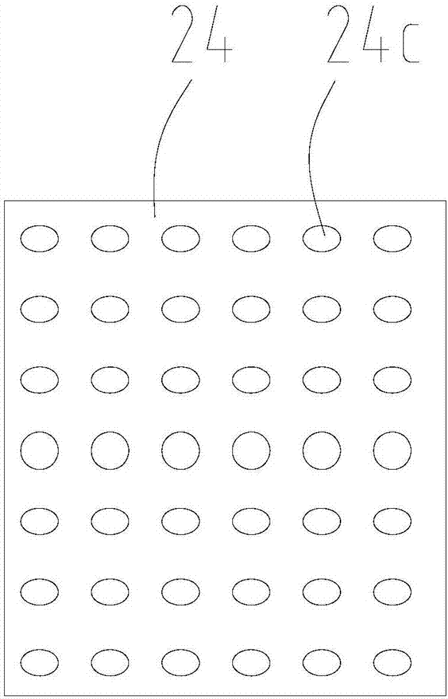
[0061] use Figure 1 to Figure 4 In the platinum channel flow control system shown, the heating regulation loop includes 4 control loops (loop 1, loop 2, loop 3, and loop 4 from the left to the right of the drawing). The gas supplied by the heat-absorbing medium supply device 21 is a mixed gas of air and water vapor. The gas temperature is adjusted to 90°C and the humidity is 60%. The liquid flow rate is 400kg / h, and the thickness of the glass plate is 0.5mm. The sleeve inner wall 24a of the outlet sleeve 24 is 150mm away from the outer surface of the platinum channel. The air outlet 24c of the air outlet sleeve 24 is circular in shape, and the area of ​​each air outlet 24c is 76mm 2 .

experiment example 2

[0063] use Figure 1 to Figure 4 In the platinum channel flow control system shown, the heating regulation loop includes 4 control loops (loop 1, loop 2, loop 3, and loop 4 from the left to the right of the drawing). The gas supplied by the heat-absorbing medium supply device 21 is a mixed gas of air and water vapor. The gas temperature is adjusted to 100°C and the humidity is 60%. The liquid flow rate is 400kg / h, and the thickness of the glass plate is 0.5mm. The sleeve inner wall 24a of the outlet sleeve 24 is 180mm away from the outer surface of the platinum channel. The air outlet 24c of the air outlet sleeve 24 is circular in shape, and the area of ​​each air outlet 24c is 60mm 2 .

experiment example 3

[0065] use Figure 4 and Figure 5In the platinum channel flow control system shown, the heating regulation loop includes 4 control loops (loop 1, loop 2, loop 3, and loop 4 from the left to the right of the drawing). The gas supplied by the heat-absorbing medium supply device 21 is a mixed gas of air and water vapor. The gas temperature is adjusted to 120°C and the humidity is 70%. The liquid flow rate is 400kg / h, and the thickness of the glass plate is 0.5mm. The sleeve inner wall 24a of the outlet sleeve 24 is 150mm away from the outer surface of the platinum channel. The air outlet 24c of the air outlet sleeve 24 is circular in shape, and the area of ​​each air outlet 24c is 60mm 2 .


PUM

PropertyMeasurementUnit
thicknessaaaaaaaaaa

Abstract

The invention relates to a platinum channel flow control system. The system comprises a platinum channel (10) for adjusting a heating adjustment return circuit of the glass liquid flow in the platinum channel, and a heat dissipation device (20) for assisting in adjusting the glass liquid flow in the platinum channel (10). The flow control system not only comprises the traditional heating adjustment return circuit for adjusting the glass liquid flow in the platinum channel, but also comprises the heat dissipation device to achieve auxiliary adjustment for the glass liquid flow, that is, glass liquid is cooled by the heat dissipation device, thereby achieving the auxiliary adjustment for the glass liquid flow. Thus, the flow control system can improve the electric heating power of the heating adjustment return circuit without increasing the number of the heating adjustment return circuits and the length of the channel, thereby improving the capacity of the heating adjustment return circuit to control the glass liquid flow, so that the fluctuation range of the glass liquid flow is smaller, the product thickness difference and stress are smaller, and the glass substrate product quality is improved.

Description

technical field [0001] The present disclosure relates to the field of glass substrate manufacturing equipment, in particular, to a platinum channel flow control system. Background technique [0002] In the manufacturing process of TFT and LTPS glass substrates, the kiln process melts the batch materials into glass liquid and then reaches the platinum channel process for clarification and homogenization. After the glass liquid passes through the platinum channel process, it is sent to the molding process to be made into semi-finished glass plates After processing, it is made into a finished product, and then it can be sent to the panel manufacturer for use after packaging and transportation. [0003] With the panel display accuracy and the market's pursuit of ultra-thin products, panel manufacturers are getting higher and higher. In turn, the requirements for the thickness, thickness range and stress of glass plate products are higher, from the required thickness of 0.7mm, th...

Claims


Application Information

Patent Timeline
Patent Type & Authority Applications(China)
IPC IPC(8): C03B5/18
CPCC03B5/18
Inventor 田红星郑权
Owner DONGXU OPTOELECTRONICS TECH CO LTD
Learn More