Sand mill circulating pump for production of high-performance metal soft magnetic ferrite

A soft ferrite, high-performance technology, used in liquid variable capacity machinery, pumps with flexible working elements, pumps, etc., can solve the problems of large changes in state and low flow, and reduce cycle time, The effect of enhanced pumping capacity, easy precision

Inactive Publication Date: 2017-08-18
马鞍山新康达磁业股份有限公司
View PDF12 Cites 1 Cited by
  • Summary
  • Abstract
  • Description
  • Claims
  • Application Information

AI Technical Summary

Problems solved by technology

[0006] Aiming at the problem that the circulation pump used in the existing sand mill circulation pulping system has a low flow rate and its state changes greatly when carrying out high and low conveying loads, the present invention provides a high-performance metal soft magnetic ferrite production Sand mill circulation pump, long-term stable and reliable operation of the circulation pump, a large flow adjustment range, and economical and energy-saving, to achieve energy saving and consumption reduction for enterprises

Method used


Image

  • Sand mill circulating pump for production of high-performance metal soft magnetic ferrite
  • Sand mill circulating pump for production of high-performance metal soft magnetic ferrite
  • Sand mill circulating pump for production of high-performance metal soft magnetic ferrite

Examples


Embodiment 1

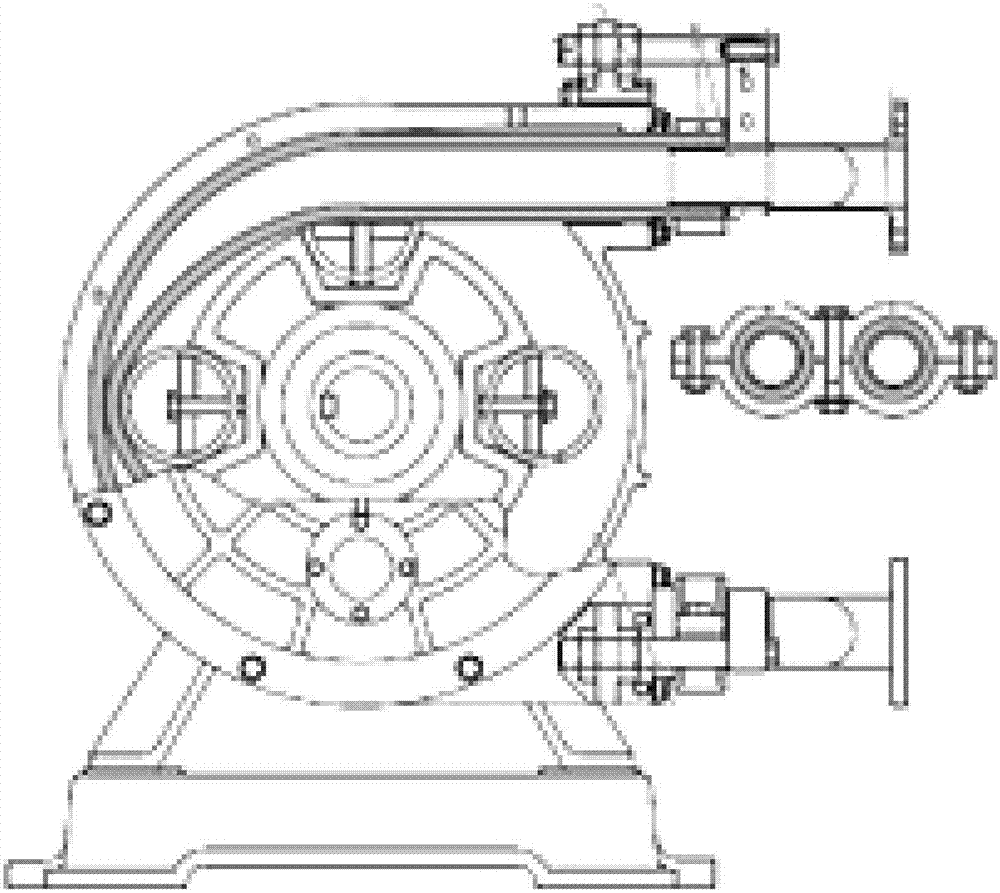
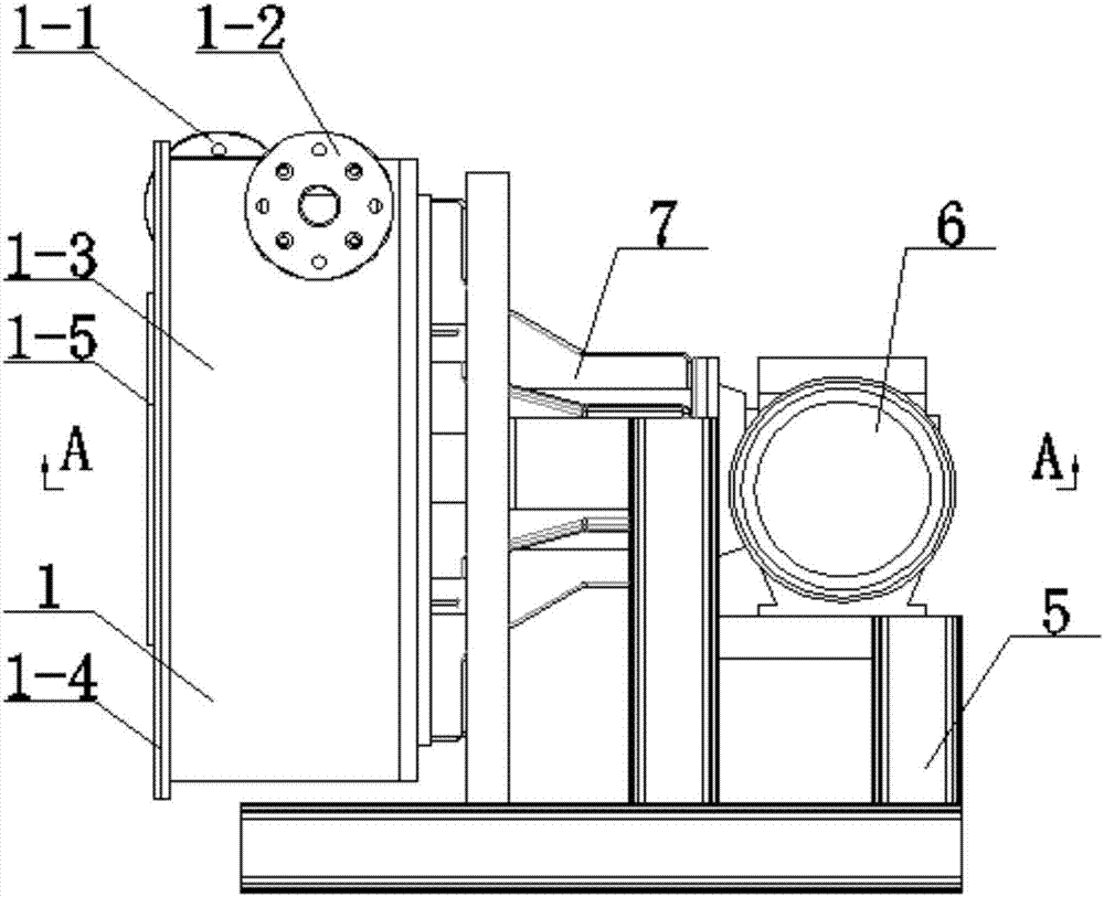
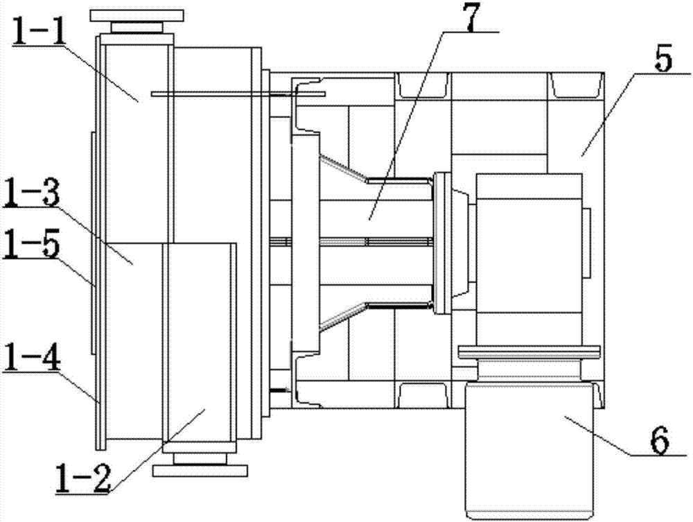
[0040] like Figure 2 to Figure 8 As shown, a sand mill circulation pump for the production of high-performance metal soft ferrite of the present invention includes a pump casing 1, a feed port 1-1 and a discharge port 1-2 arranged on the pump casing 1, and a crankshaft 2. Extrusion roller 3, hose 4, deceleration motor 6 and bearing housing 7 fixedly installed on base 5, feed inlet 1-1 and discharge outlet 1-2 are staggered horizontally by 180°, hose 4 The two ends are respectively connected to the material inlet 1-1 and the material outlet 1-2, and material sensors (not marked in the figure) are arranged in the material inlet 1-1 and the material outlet 1-2, and the center of the hose 4 The axis is located on the spiral surface, the crankshaft 2 is inserted in the bearing seat 7, and connected with the reduction motor 6, the extrusion roller 3 is fixed on the crankshaft 2, and the crankshaft 2 drives the extrusion roller 3 to squeeze the hose 4, which solves the current cycle...

Embodiment 2

[0047] Because the inner tube 4-1 is made of rubber material, when the hose 4 pump is working, the hose 4 is flattened by the extruding body, the deformation is very large, and the inside bears relatively large pressure and the friction formed by the fluid flow. With the continuous rotation of the extrusion roller 3, these forces are repeatedly applied to the hose 4, and the extrusion deformation and friction of the extrusion body on the surface of the hose 4 will increase the temperature of the hose 4 , which accelerates the aging of the hose 4, so the inner tube 4-1 is set in the protective sleeve 4-2, such as Figure 8 In the structure shown, the extrusion roller 3 is in contact with the protective sleeve 4-2 instead of the inner tube 4-1, and the protective sleeve 4-2 can well protect the inner tube 4-1 and reduce the wear of the inner tube 4-1. Extend the service life of the hose 4.

[0048] The circulation pump of the present invention is installed in the slurry circula...

Embodiment 3

[0050] In the actual use process, in order to facilitate the observation of the internal conditions of the pump casing 1 through the panels 1-5, judge the wear of the hose 4 and the extrusion roller 3, and facilitate the timely replacement of the hose 4 end caps 1-4. The center is provided with an observation hole , A panel 1-5 is installed on the observation hole, and the panel 1-5 is made of transparent toughened glass, wired glass, explosion-proof glass or acrylic material.


PUM


Abstract

The invention discloses a sand mill circulating pump for producing metal soft ferrite with high performance, belonging to the technical field of soft ferrite production. It includes the pump casing, the feed inlet and outlet set on the pump casing, the crankshaft, the extrusion roller, the hose, the geared motor and the bearing seat fixedly installed on the base, and the feed inlet and outlet are 180° Horizontal staggered arrangement, one end of the hose is connected to the material inlet, and the other end is connected to the material outlet. The central axis of the hose is located on the spiral surface. The crankshaft is passed through the bearing seat and connected to the geared motor. The extrusion roller is fixed on the crankshaft. The crankshaft drives the squeeze rollers to squeeze the hose. The invention adopts 180°horizontal staggered arrangement of the feed inlet and the discharge outlet, which solves the problem that the slurry flow rate is not high, and its state changes greatly when carrying out high and low conveying loads. Extrusion dead angle will be produced, so that the accuracy can be easily and precisely controlled.

Description

technical field [0001] The invention belongs to the technical field of soft ferrite production, and more specifically relates to a sand mill circulation pump for high-performance metal soft ferrite production. Background technique [0002] The sand mill has been widely used in the industry as a crushing equipment for ferrite magnetic materials. It is mainly composed of a cylinder, a stirring rod, a discharge valve, a motor and a circulation pump. It uses water as the grinding liquid and steel balls or zirconia balls as the grinding material. Medium, crush ferrite powder into ultra-fine powder ranging from a few tenths of microns to tens of microns, and the ground powder is generally fed by a circulating pump, with high inflow and low outflow, repeating itself, according to the length of the cycle, the coarser powder Powders with different particle sizes are ground into fine powders with different particle size requirements. In view of this working principle, the sand mill i...

Claims


Application Information

Patent Timeline
Patent Type & Authority Applications(China)
IPC IPC(8): F04B43/12
CPCF04B43/1246
Inventor 王利锋赵光陈小林彭科铭
Owner 马鞍山新康达磁业股份有限公司
Why Eureka
Try Eureka